SECTION 4 - BOOM & PLATFORM
4-4
– JLG Lift –
3121827
4.2 UPPER (MAIN) BOOM LIFT CYLINDER
Removal
1.
Place the machine on a flat and level surface. Place
the Upper Boom in a horizontal position. Place
Lower and Mid Booms 5 degree above horizontal.
Shut down machine and prop boom.
2.
Tag, disconnect and cap the upper boom lift cylinder
hydraulic lines and ports.
3.
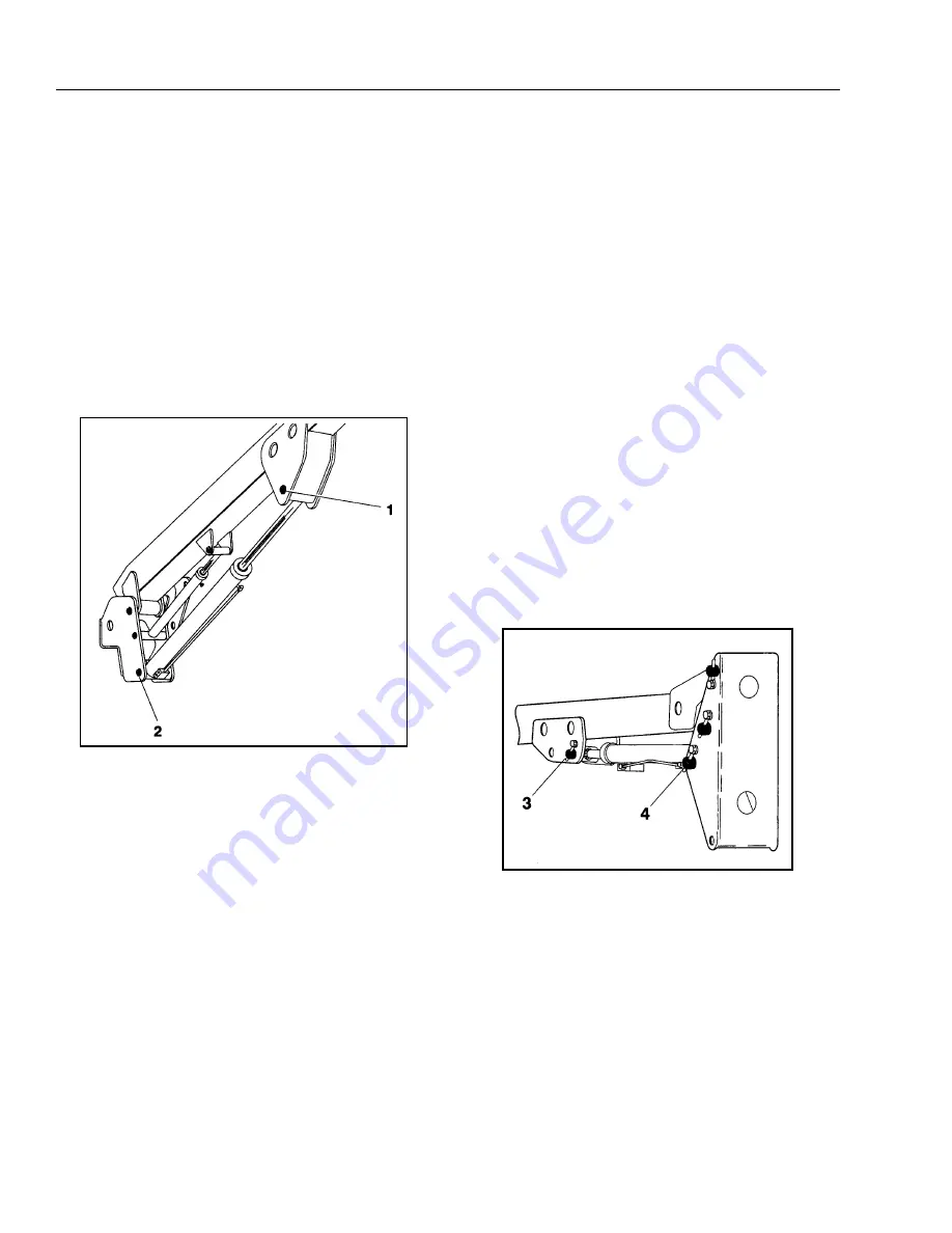
Remove the hardware securing the cylinder rod
attach pin #1 to the boom. Using a suitable brass
drift, drive out the cylinder rod attach pin #1
.
4.
Secure the cylinder with suitable slings or supports
as required. Remove the hardware securing the bar-
rel end attach pin #2. Using a suitable brass drift,
drive out the barrel end attach pin #2.
5.
Remove the cylinder from the boom and place in a
suitable work area.
Installation
NOTE:
Coat I.D. of bushings with specified lubricant prior to
installing pins.
1.
Install Lift Cylinder in place using suitable slings or
supports, aligning attach pin mounting holes on
upright.
2.
Using a suitable drift, drive the barrel end attach pin
#2 through the mounting holes in the lift cylinder
and upright. Secure in place with pin retaining hard-
ware.
3.
Remove cylinder port plugs and hydraulic line caps
and correctly attach lines to cylinder ports.
4.
With function speed switch at its slowest setting,
extend the cylinder rod until attach pin hole aligns
with those in boom. Using a suitable drift, drive the
cylinder rod attach pin #1 through the aligned
holes. Secure the pin in place with pin retaining
hardware.
5.
Cycle cylinder completely to check for proper func-
tioning. Place boom in stowed position. Check
hydraulic fluid level and adjust accordingly.
4.3 MID BOOM LIFT CYLINDER
Removal
1.
Place machine on flat and level surface. Place the
Upper Boom in a horizontal position. Place the Mid
Boom in a 10 degree elevated position. Support
Upper Boom with a prop. Support upright with an
overhead crane.
2.
Using slings, restrain the lower lift cylinder.
3.
Remove the hardware securing the cylinder rod
attach pin #3 to the boom. Using an appropriate
brass drift, drive out the cylinder rod attach pin #3.
4.
Tag, disconnect and cap the lift cylinder hydraulic
lines and ports.
5.
Remove the hardware securing the barrel end attach
pin #4 to the boom. Using an appropriate brass
drift, drive out the cylinder barrel pin #4.
6.
Carefully remove cylinder from boom. Place in a
suitable work area.
Figure 4-2. Upper Boom Lift Cylinder Removal
Figure 4-3. Mid Boom Lift Cylinder Removal
Summary of Contents for JLG E400AJP
Page 2: ......
Page 32: ...SECTION 1 SPECIFICATIONS 1 18 JLG Lift 3121827 NOTES...
Page 42: ...SECTION 2 GENERAL 2 10 JLG Lift 3121827 NOTES...
Page 54: ...SECTION 3 CHASSIS TURNTABLE 3 12 JLG Lift 3121827 Figure 3 3 Speed Sensor Orientation...
Page 60: ...SECTION 3 CHASSIS TURNTABLE 3 18 JLG Lift 3121827 Figure 3 7 Steering Components and Spindles...
Page 62: ...SECTION 3 CHASSIS TURNTABLE 3 20 JLG Lift 3121827 Figure 3 9 Tilt Sensor Location...
Page 86: ...SECTION 3 CHASSIS TURNTABLE 3 44 JLG Lift 3121827 Figure 3 16 Swing Components...
Page 88: ...SECTION 3 CHASSIS TURNTABLE 3 46 JLG Lift 3121827 Figure 3 18 Battery Cable Connections...
Page 90: ...SECTION 3 CHASSIS TURNTABLE 3 48 JLG Lift 3121827 Figure 3 20 On Board Generator...
Page 97: ...SECTION 3 CHASSIS TURNTABLE 3121827 JLG Lift 3 55 Figure 3 22 Generator Components...
Page 116: ...SECTION 3 CHASSIS TURNTABLE 3 74 JLG Lift 3121827 NOTES...
Page 127: ...SECTION 4 BOOM PLATFORM 3121827 JLG Lift 4 11 Figure 4 10 Boom Limit Switches...
Page 140: ...SECTION 4 BOOM PLATFORM 4 24 JLG Lift 3121827 Figure 4 13 Rotator Counterbalance Valve...
Page 178: ...SECTION 5 HYDRAULICS 5 24 JLG Lift 3121827 Figure 5 26 HydraForce Cartridge Torque Value Chart...
Page 214: ...SECTION 6 JLG CONTROL SYSTEM 6 34 JLG Lift 3121827 NOTES...
Page 257: ......


