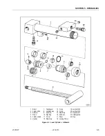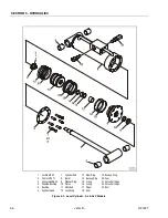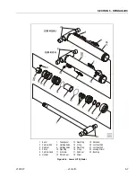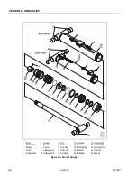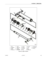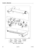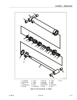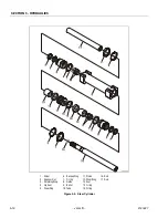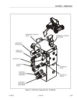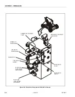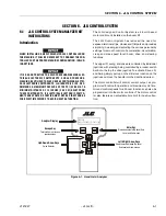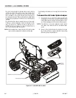
SECTION 5 - HYDRAULICS
3121827
– JLG Lift –
5-15
5.
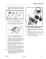
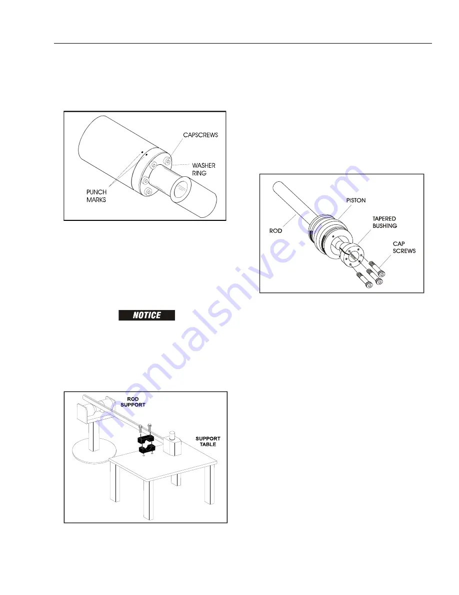
Mark cylinder head and barrel with a center punch
for easy realignment. Using an allen wrench, loosen
the cylinder head retainer cap screws, and remove
cap screws from cylinder barrel.
NOTE:
Steps 6 applies only to the lower lift and telescope
cylinders.
6.
Using a spanner wrench, loosen the end cap or
head retainer, and remove from cylinder barrel.
7.
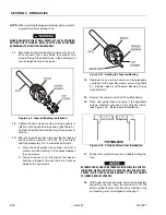
Attach a suitable pulling device to the cylinder rod
port block end or cylinder rod end, as applicable.
EXTREME CARE SHOULD BE TAKEN WHEN REMOVING THE CYL-
INDER ROD, HEAD, AND PISTON. AVOID PULLING THE ROD OFF-
CENTER, WHICH COULD CAUSE DAMAGE TO THE PISTON AND
CYLINDER BARREL SURFACES.
8.
With the barrel clamped securely, apply pressure to
the rod pulling device and carefully withdraw the
complete rod assembly from the cylinder barrel.
9.
Using suitable protection, clamp the cylinder rod in
a vise or similar holding fixture as close to the piston
as possible.
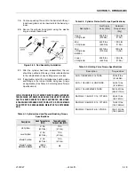
10.
Loosen and remove the cap screw(s), if applicable,
which attach the tapered bushing to the piston.
11.
Insert the cap screw(s) in the threaded holes in the
outer piece of the tapered bushing. Progressively
tighten the cap screw(s) until the bushing is loose
on the piston.
12.
Remove the bushing from the piston.
13.
Screw the piston CCW, by hand, and remove the
piston from cylinder rod.
14.
Remove and discard the piston o-rings, seal rings,
and backup rings.
15.
Remove piston spacer, if applicable, from the rod.
16.
Remove the rod from the holding fixture. Remove
the cylinder head gland and retainer plate, if applica-
ble. Discard the o-rings, back-up rings, rod seals,
and wiper seals.
Cleaning and Inspection
1.
Clean all parts thoroughly in an approved cleaning
solvent.
2.
Inspect the cylinder rod for scoring, tapering, ovality,
or other damage. If necessary, dress rod with
Scotch Brite or equivalent. Replace rod if necessary.
3.
Inspect threaded portion of rod for excessive dam-
age. Dress threads as necessary.
4.
Inspect inner surface of cylinder barrel tube for scor-
ing or other damage. Check inside diameter for
tapering or ovality. Replace if necessary.
5.
Inspect threaded portion of barrel for damage. Dress
threads as necessary.
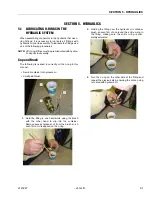
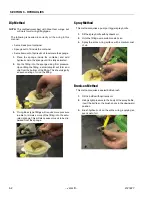
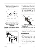
Figure 5-12. Capscrew Removal
Figure 5-13. Cylinder Rod Support
Figure 5-14. Tapered Bushing
Summary of Contents for JLG E400AJP
Page 2: ......
Page 32: ...SECTION 1 SPECIFICATIONS 1 18 JLG Lift 3121827 NOTES...
Page 42: ...SECTION 2 GENERAL 2 10 JLG Lift 3121827 NOTES...
Page 54: ...SECTION 3 CHASSIS TURNTABLE 3 12 JLG Lift 3121827 Figure 3 3 Speed Sensor Orientation...
Page 60: ...SECTION 3 CHASSIS TURNTABLE 3 18 JLG Lift 3121827 Figure 3 7 Steering Components and Spindles...
Page 62: ...SECTION 3 CHASSIS TURNTABLE 3 20 JLG Lift 3121827 Figure 3 9 Tilt Sensor Location...
Page 86: ...SECTION 3 CHASSIS TURNTABLE 3 44 JLG Lift 3121827 Figure 3 16 Swing Components...
Page 88: ...SECTION 3 CHASSIS TURNTABLE 3 46 JLG Lift 3121827 Figure 3 18 Battery Cable Connections...
Page 90: ...SECTION 3 CHASSIS TURNTABLE 3 48 JLG Lift 3121827 Figure 3 20 On Board Generator...
Page 97: ...SECTION 3 CHASSIS TURNTABLE 3121827 JLG Lift 3 55 Figure 3 22 Generator Components...
Page 116: ...SECTION 3 CHASSIS TURNTABLE 3 74 JLG Lift 3121827 NOTES...
Page 127: ...SECTION 4 BOOM PLATFORM 3121827 JLG Lift 4 11 Figure 4 10 Boom Limit Switches...
Page 140: ...SECTION 4 BOOM PLATFORM 4 24 JLG Lift 3121827 Figure 4 13 Rotator Counterbalance Valve...
Page 178: ...SECTION 5 HYDRAULICS 5 24 JLG Lift 3121827 Figure 5 26 HydraForce Cartridge Torque Value Chart...
Page 214: ...SECTION 6 JLG CONTROL SYSTEM 6 34 JLG Lift 3121827 NOTES...
Page 257: ......

