


SECTION 3 - CHASSIS & TURNTABLE
3121827
– JLG Lift –
3-33
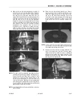
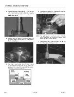
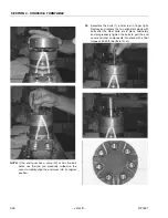
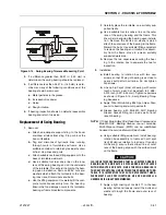
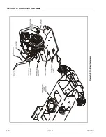
8.
Be sure that a generous amount of clean corrosion
resistant grease has been applied to the lower
(outer) housing bearing/bushing (19). Install the
coupling shaft (12) into housing (18), seating it
against the thrust bearing (15).
THE OUTER BEARING (19) IS NOT LUBRICATED BY THE SYS-
TEM’S HYDRAULIC FLUID. BE SURE IT IS THOROUGHLY PACKED
WITH THE RECOMMENDED GREASE.
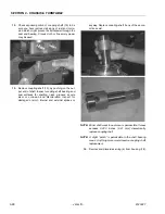
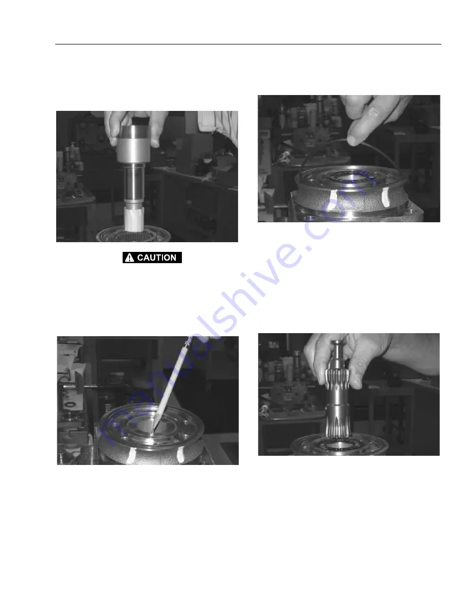
NOTE:
The coupling shaft (12) will be flush or just below the
housing wear surface when properly seated while
the coupling shaft (12). The coupling shaft must
rotate smoothly on the thrust bearing package.
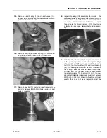
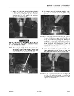
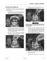
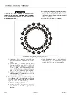
9.
Apply a small amount of clean grease to a new seal
ring (4) and insert it into the housing (18) seal ring
groove.
NOTE:
One or two alignment studs screwed finger tight into
housing (18) bolt holes, approximately 180 degrees
apart, will facilitate the assembly and alignment of
components as required in the following procedures.
The studs can be made by cutting off the heads of
either 3/8-24 UNF 2A or 5/16-24 UNF 2A bolts as
required that are over 0.5 inch (12.7 mm) longer than
the bolts (1) used in the motor.
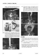
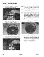
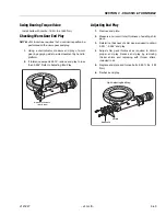
10.
Install drive link (10) the long splined end down into
the coupling shaft (12) and engage the drive link
splines into mesh with the coupling shaft splines.
NOTE:
Use any alignment marks put on the coupling shaft
and drive link before disassembly to assemble the
drive link splines in their original position in the mat-
ing coupling shaft splines.
Summary of Contents for JLG E400AJP
Page 2: ......
Page 32: ...SECTION 1 SPECIFICATIONS 1 18 JLG Lift 3121827 NOTES...
Page 42: ...SECTION 2 GENERAL 2 10 JLG Lift 3121827 NOTES...
Page 54: ...SECTION 3 CHASSIS TURNTABLE 3 12 JLG Lift 3121827 Figure 3 3 Speed Sensor Orientation...
Page 60: ...SECTION 3 CHASSIS TURNTABLE 3 18 JLG Lift 3121827 Figure 3 7 Steering Components and Spindles...
Page 62: ...SECTION 3 CHASSIS TURNTABLE 3 20 JLG Lift 3121827 Figure 3 9 Tilt Sensor Location...
Page 86: ...SECTION 3 CHASSIS TURNTABLE 3 44 JLG Lift 3121827 Figure 3 16 Swing Components...
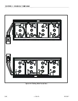
Page 88: ...SECTION 3 CHASSIS TURNTABLE 3 46 JLG Lift 3121827 Figure 3 18 Battery Cable Connections...
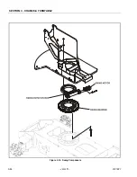
Page 90: ...SECTION 3 CHASSIS TURNTABLE 3 48 JLG Lift 3121827 Figure 3 20 On Board Generator...
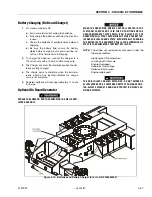
Page 97: ...SECTION 3 CHASSIS TURNTABLE 3121827 JLG Lift 3 55 Figure 3 22 Generator Components...
Page 116: ...SECTION 3 CHASSIS TURNTABLE 3 74 JLG Lift 3121827 NOTES...
Page 127: ...SECTION 4 BOOM PLATFORM 3121827 JLG Lift 4 11 Figure 4 10 Boom Limit Switches...
Page 140: ...SECTION 4 BOOM PLATFORM 4 24 JLG Lift 3121827 Figure 4 13 Rotator Counterbalance Valve...
Page 178: ...SECTION 5 HYDRAULICS 5 24 JLG Lift 3121827 Figure 5 26 HydraForce Cartridge Torque Value Chart...
Page 214: ...SECTION 6 JLG CONTROL SYSTEM 6 34 JLG Lift 3121827 NOTES...
Page 257: ......


