SECTION 3 - CHASSIS & TURNTABLE
3121827
– JLG Lift –
3-25
3.
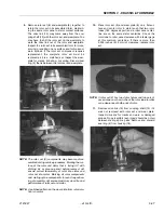
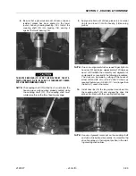
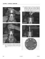
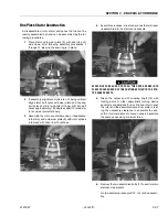
Remove the special ring head bolts (1) using an
appropriate 1/2 or 9/16 inch size socket. Inspect
bolts for damaged threads, or sealing rings, under
the bolt head. Replace damaged bolts.
4.
Remove end cover assembly (2) and seal ring (4).
Discard seal ring.
5.
Thoroughly wash end cover (2) in proper solvent
and blow dry. Be sure the end cover valve apertures
are free of contamination. Inspect end cover for
cracks and the bolt head recesses for good bolt
head sealing surfaces. Replace end cover as neces-
sary.
NOTE:
A polished pattern (not scratches) on the cover from
rotation of the commutator (5) is normal. Discolor-
ation would indicate excess fluid temperature, ther-
mal shock, or excess speed and require system
investigation for cause and close inspection of end
cover, commutator, manifold, and rotor set.
6.
Remove commutator ring (6). Inspect commutator
ring for cracks, or burrs.
Summary of Contents for JLG E400AJP
Page 2: ......
Page 32: ...SECTION 1 SPECIFICATIONS 1 18 JLG Lift 3121827 NOTES...
Page 42: ...SECTION 2 GENERAL 2 10 JLG Lift 3121827 NOTES...
Page 54: ...SECTION 3 CHASSIS TURNTABLE 3 12 JLG Lift 3121827 Figure 3 3 Speed Sensor Orientation...
Page 60: ...SECTION 3 CHASSIS TURNTABLE 3 18 JLG Lift 3121827 Figure 3 7 Steering Components and Spindles...
Page 62: ...SECTION 3 CHASSIS TURNTABLE 3 20 JLG Lift 3121827 Figure 3 9 Tilt Sensor Location...
Page 86: ...SECTION 3 CHASSIS TURNTABLE 3 44 JLG Lift 3121827 Figure 3 16 Swing Components...
Page 88: ...SECTION 3 CHASSIS TURNTABLE 3 46 JLG Lift 3121827 Figure 3 18 Battery Cable Connections...
Page 90: ...SECTION 3 CHASSIS TURNTABLE 3 48 JLG Lift 3121827 Figure 3 20 On Board Generator...
Page 97: ...SECTION 3 CHASSIS TURNTABLE 3121827 JLG Lift 3 55 Figure 3 22 Generator Components...
Page 116: ...SECTION 3 CHASSIS TURNTABLE 3 74 JLG Lift 3121827 NOTES...
Page 127: ...SECTION 4 BOOM PLATFORM 3121827 JLG Lift 4 11 Figure 4 10 Boom Limit Switches...
Page 140: ...SECTION 4 BOOM PLATFORM 4 24 JLG Lift 3121827 Figure 4 13 Rotator Counterbalance Valve...
Page 178: ...SECTION 5 HYDRAULICS 5 24 JLG Lift 3121827 Figure 5 26 HydraForce Cartridge Torque Value Chart...
Page 214: ...SECTION 6 JLG CONTROL SYSTEM 6 34 JLG Lift 3121827 NOTES...
Page 257: ......


