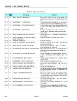
SECTION 6 - JLG CONTROL SYSTEM
3121827
– JLG Lift –
6-31
33364
33
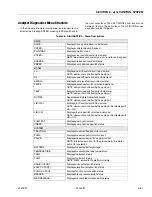
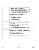
FORWARD CONTACTOR COIL - OPEN CIRCUIT
Traction point A did not go HIGH when forward contactor was
energized. This maybe due to an open circuit traction motor or
power wiring error
33369
33
REVERSE CONTACTOR COIL - OPEN CIRCUIT
Traction point A did not go HIGH when reverse contactor was
energized. This maybe due to an open circuit traction motor or
power wiring error
33370
33
FORWARD CONTACTOR COIL - SHORT CIRCUIT
The forward contactor was not energized when required, due to
over current protection
33371
33
REVERSE CONTACTOR COIL - SHORT CIRCUIT
The reverse contactor was not energized when required, due to
over current protection
33411
33
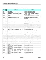
VALVE SUPPLY OVERLOADED
There is a high current draw from the valve supply when no valve
is energized; this maybe due to a wiring error at the ground mod-
ule
421
42
POWER MODULE TOO HOT - PLEASE WAIT
Controller heat sink temperature reached 75*C, the controller is
shut down until it cools to below 70*C
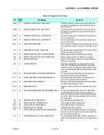
441
44
BATTERY VOLTAGE TOO LOW - SYSTEM SHUTDOWN
Battery voltage is below 33 volts EMS recycle is required
442
44
BATTERY VOLTAGE TOO HIGH - SYSTEM SHUTDOWN
Battery voltage is above 62 volts, EMS recycle is required
445
44
BATTERY VOLTAGE LOW
Battery voltage is below 40 volts, this is only a warning, the con-
troller does not shut down
469
46
VEHICLE OVERSPEED
Speed in the wrong direction was measured with the traction
motor full ON. This maybe due to a faulty speed sensor being
installed incorrectly; it could also be due to a speed sensor fault or
faults for NO VEHICLE MOVEMENT DETECTED with the vehicle
on a grade
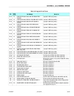
4610
46
RIGHT SPEED SENSOR - NOT RESPONDING PROPERL Y
The right speed sensor is indicating an impossible number of
pulses, this maybe due to a faulty speed sensor
4611
46
LEFT SPEED SENSOR - NOT RESPONDING PROPERL Y
The left speed sensor is indicating an impossible number of
pulses, this maybe due to a faulty speed sensor
4615
46
SPEED SENSOR - INVALID READING
Both speed sensors are indicating impossible number of pulses,
this maybe due to a faulty speed sensor
4616
46
BRAKES DID NOT LOCK
Brake pressure did not clear when the brake valve was de- ener-
gized
4617
46
NO VEHICLE MOVEMENT DETECTED AT MAXIMUM POWER
No speed was measured with the traction motor full ON. This
could be due to a traction motor fault, a power wiring error, a
speed sensor fault, the brakes not releasing (though brake pres-
sure is OK) or the vehicle being overloaded so that the motor can-
not turn the wheels
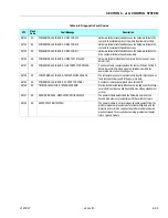
661
66
CANBUS FAILURE - POWER MODULE
Power Module CAN communication lost.
662
66
CAN BUS FAILURE - PLATFORM MODULE
Platform Module CAN communication lost.
6631
66
CAN BUS FAILURE - GROUND MODULE
Ground Module CAN communication lost.
6636
66
CANBUS FAILURE - TILT MODULE
Tilt Module CAN communication lost.
772
77
STALLED TRACTION MOTOR OR POWER WIRING ERROR
The power module traction MOSFET protection circuit is active,
This is due to a massive current drain and could be a stalled trac-
tion motor or a power wiring error
773
77
CAPACITOR BANK FAULT - CHECK POWER CIRCUITS
The capacitor bank is not charging, this maybe due to a power
wiring error causing illegal current drain or a very low battery volt-
age
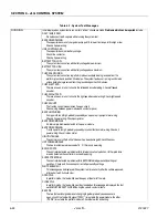
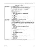
Table 6-8. Diagnostic Fault Codes
DTC
Flash
Code
Fault Message
Description
Summary of Contents for JLG E400AJP
Page 2: ......
Page 32: ...SECTION 1 SPECIFICATIONS 1 18 JLG Lift 3121827 NOTES...
Page 42: ...SECTION 2 GENERAL 2 10 JLG Lift 3121827 NOTES...
Page 54: ...SECTION 3 CHASSIS TURNTABLE 3 12 JLG Lift 3121827 Figure 3 3 Speed Sensor Orientation...
Page 60: ...SECTION 3 CHASSIS TURNTABLE 3 18 JLG Lift 3121827 Figure 3 7 Steering Components and Spindles...
Page 62: ...SECTION 3 CHASSIS TURNTABLE 3 20 JLG Lift 3121827 Figure 3 9 Tilt Sensor Location...
Page 86: ...SECTION 3 CHASSIS TURNTABLE 3 44 JLG Lift 3121827 Figure 3 16 Swing Components...
Page 88: ...SECTION 3 CHASSIS TURNTABLE 3 46 JLG Lift 3121827 Figure 3 18 Battery Cable Connections...
Page 90: ...SECTION 3 CHASSIS TURNTABLE 3 48 JLG Lift 3121827 Figure 3 20 On Board Generator...
Page 97: ...SECTION 3 CHASSIS TURNTABLE 3121827 JLG Lift 3 55 Figure 3 22 Generator Components...
Page 116: ...SECTION 3 CHASSIS TURNTABLE 3 74 JLG Lift 3121827 NOTES...
Page 127: ...SECTION 4 BOOM PLATFORM 3121827 JLG Lift 4 11 Figure 4 10 Boom Limit Switches...
Page 140: ...SECTION 4 BOOM PLATFORM 4 24 JLG Lift 3121827 Figure 4 13 Rotator Counterbalance Valve...
Page 178: ...SECTION 5 HYDRAULICS 5 24 JLG Lift 3121827 Figure 5 26 HydraForce Cartridge Torque Value Chart...
Page 214: ...SECTION 6 JLG CONTROL SYSTEM 6 34 JLG Lift 3121827 NOTES...
Page 257: ......


