SECTION 6 - JLG CONTROL SYSTEM
3121827
– JLG Lift –
6-13
2/2
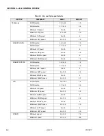
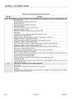
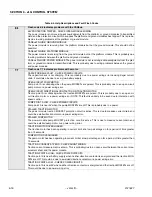
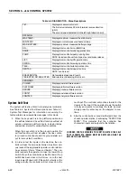
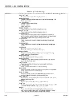
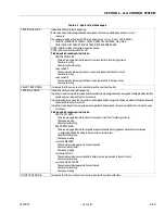
Flash code 2/2 indicates problems with drive & steer selection.
DRIVE JOYSTICK FAULTY
The drive joystick center tap is out of valid range, or the wiper is wire-off.
DRIVE LOCKED - JOYSTICK MOVED BEFORE EMS/FWS
Drive was selected before and during footswitch closure.
FWS INTERLOCK TRIPPED
Footswitch was closed for seven seconds with no function selected.
STEER LOCKED - SELECTED BEFORE EMS/FWS
Steer was selected before and during footswitch closure.
STEER SWITCHES FAULTY
Both steer switches are active together.
WAITING FOR FWS TO BE OPEN
Footswitch was closed when platform mode was selected.
JOYSTICK FAULTS - CHECK PLATFORM BOX WIRING
More than one of the drive, lift and swing joystick center tap or wiper voltages is out of range.
This is probably due to a short-circuit across a joystick port.
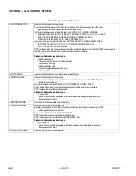
2/3
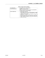
Flash code 2/3 indicates problems with boom function selection.
LIFT/SWING JOYSTICK FAULTY
The lift or swing Joystick center tap is out of valid range, or the wiper is wire-off.
LIFT/SWING LOCKED - JOYSTICK MOVED BEFORE EMS/FWS
Upper Lift or swing was selected before and during footswitch closure.
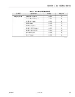
PUMP POT FAULTY
The pump pot is open-circuit; all platform boom functions except upper lift & swing will run at creep.
PUMP SWITCHES FAULTY - CHECK DIAGNOSTICS/BOOM
A boom function (lower lift, telescope, basket level, basket rotate, jib) has both directions selected together.
PUMP SWITCHES LOCKED - SELECTED BEFORE EMS/FWS
A boom function (lower lift, telescope, basket level, basket rotate, jib) was selected before and during foot-
switch closure.
PUMP SWITCHED LOCKED - SELECTED BEFORE EMS
A ground boom function (lower lift, telescope, basket level, basket rotate, jib) was selected before key-
switch.
SWING/LIFT JOYSTICK FAULTY
The swing joystick center tap is out of valid range, or the wiper is wire-off.
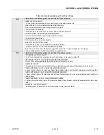
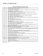
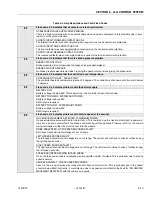
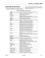
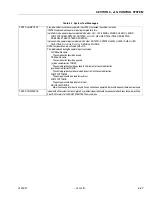
Table 6-4. Help Descriptions and Fault Flash Codes
Summary of Contents for JLG E400AJP
Page 2: ......
Page 32: ...SECTION 1 SPECIFICATIONS 1 18 JLG Lift 3121827 NOTES...
Page 42: ...SECTION 2 GENERAL 2 10 JLG Lift 3121827 NOTES...
Page 54: ...SECTION 3 CHASSIS TURNTABLE 3 12 JLG Lift 3121827 Figure 3 3 Speed Sensor Orientation...
Page 60: ...SECTION 3 CHASSIS TURNTABLE 3 18 JLG Lift 3121827 Figure 3 7 Steering Components and Spindles...
Page 62: ...SECTION 3 CHASSIS TURNTABLE 3 20 JLG Lift 3121827 Figure 3 9 Tilt Sensor Location...
Page 86: ...SECTION 3 CHASSIS TURNTABLE 3 44 JLG Lift 3121827 Figure 3 16 Swing Components...
Page 88: ...SECTION 3 CHASSIS TURNTABLE 3 46 JLG Lift 3121827 Figure 3 18 Battery Cable Connections...
Page 90: ...SECTION 3 CHASSIS TURNTABLE 3 48 JLG Lift 3121827 Figure 3 20 On Board Generator...
Page 97: ...SECTION 3 CHASSIS TURNTABLE 3121827 JLG Lift 3 55 Figure 3 22 Generator Components...
Page 116: ...SECTION 3 CHASSIS TURNTABLE 3 74 JLG Lift 3121827 NOTES...
Page 127: ...SECTION 4 BOOM PLATFORM 3121827 JLG Lift 4 11 Figure 4 10 Boom Limit Switches...
Page 140: ...SECTION 4 BOOM PLATFORM 4 24 JLG Lift 3121827 Figure 4 13 Rotator Counterbalance Valve...
Page 178: ...SECTION 5 HYDRAULICS 5 24 JLG Lift 3121827 Figure 5 26 HydraForce Cartridge Torque Value Chart...
Page 214: ...SECTION 6 JLG CONTROL SYSTEM 6 34 JLG Lift 3121827 NOTES...
Page 257: ......

