background image


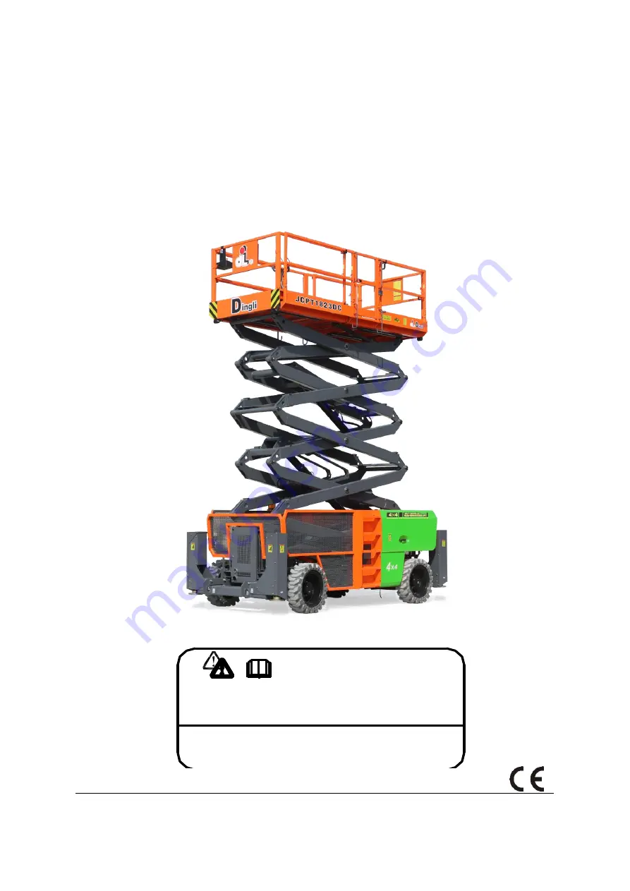
SELF-PROPELLED ROUGH-TERRAIN SCISSOR LIFTS 

OPERATOR

’S MANUAL 

with Maintenance Information 

( For JCPT1523DC / JCPT1823DC ) 


Part Number: SM0121121_Rev1.0


Zhejiang Dingli Machinery Co., Ltd. 

First Edition, April 2021 

WARNING

THE MANUFACTURER SHALL NOT BE HELD LIABLE IN CASE OF FAULTS

OR ACCIDENTS DUE TO NEGLIGENCE, INCAPACITY, INSTALLATION BY
UNQUALIFIED TECHNICIANS AND IMPROPER USE OF THE MACHINE

DO NOT OPERATE THIS MACHINE UNTIL YOU READ AND UNDERSTAND

ALL THE DANGERS,WARNINGS AND CAUTIONS IN THIS MANUAL

Summary of Contents for JCPT1523DC

Page 1: ...ejiang Dingli Machinery Co Ltd First Edition April 2021 WARNING THE MANUFACTURER SHALL NOT BE HELD LIABLE IN CASE OF FAULTS OR ACCIDENTS DUE TO NEGLIGENCE INCAPACITY INSTALLATION BY UNQUALIFIED TECHNICIANS AND IMPROPER USE OF THE MACHINE DO NOT OPERATE THIS MACHINE UNTIL YOU READ AND UNDERSTAND ALL THE DANGERS WARNINGS AND CAUTIONS IN THIS MANUAL ...

Page 2: ...OPERATOR S MANUAL with Maintenance Information Version of the Record i Version of the Record Version Number Create Date SM0121121_Rev1 0 2021 06 ...

Page 3: ......

Page 4: ... Owners Users and operators We appreciate your choice of our machine for your application Our number one priority is user safety which is best achieved by our joint efforts We feel that you make a major contribution to safety if you as the equipment users and operators 1 Comply with employer job site and governmental rules 2 Read understand and follow the instructions in this and other manuals sup...

Page 5: ......

Page 6: ...u read understand and obey all applicable governmental regulations You are properly trained to safely operate the machine Decal Legend DINGLI product decals use symbols color coding and signal words to identify the following Safety alert symbol used to alert personnel to potential personal injury hazards Obey all safety messages that follow this symbol to avoid possible injury or death Red used to...

Page 7: ...mity to electrical current Maintain safe distances from electrical power lines and apparatus in accordance with applicable governmental regulations and the following chart Voltage Phase to Phase Minimum Safe Approach Distance Meters 0 to 300V Avoid Contact 300V to 50kV 3 05 50kV to 200kV 4 60 200kV to 350kV 6 10 350kV to 500kV 7 62 500kV to 750kV 10 67 750kV to 1000kV 13 72 Allow for platform move...

Page 8: ...ounds on the chassis and in the platform when the machine is on a slope If the tilt alarm sounds Lower the platform Move the machine to a firm level surface If the tilt alarm sounds when the platform is raised use extreme caution to lower the platform For outdoor use machine Do not raise the platform when wind speeds may exceed 12 5 m s If wind speeds exceed 12 5 m s when the platform is raised lo...

Page 9: ...lter an aerial work platform without prior written permission from the manufacturer Mounting attachments for holding tools or other materials onto the platform toe boards or guard rail system can increase the weight in the platform and the surface area of the platform or the load Do not place ladders or scaffolds in the platform or against any part of this machine Do not transport tools and materi...

Page 10: ... platform unless the machine is in the stowed position Collision Hazard Be aware of limited sight distance and blind spots when driving or operating Be aware of extended platform position s when moving the machine Check the work area for overhead obstructions or other possible hazards Be aware of crushing hazards when grasping the platform guard rail Operators must comply with employer job site an...

Page 11: ...cess by the operator is only advised when performing a pre operation inspection All compartments must remain closed and secured during operation Outrigger Safety Do not lower the outriggers unless the machine is on a firm surface If the ground does not meet the requirements specified of the relevant regulations sufficient ground preparation shall be carried out in advance to confirm its safety bef...

Page 12: ...es and lighted tobacco away from batteries Batteries emit explosive gas Electrocution Hazard Avoid contact with electrical terminals Pollute Hazard Dispose of old battery must comply with job site and governmental rules Lockout after Each Use 1 Select a safe parking location firm level surface clear of obstructions and traffic 2 Lower the platform 3 Turn the key switch to the off position and remo...

Page 13: ...r housing 2 Platform extension lock handle 10 Outrigger footpads 3 Platform entry gate 11 Steer tire 4 Platform controls 12 Entry ladder 5 Platform guard rails 13 Batteries tray behind cover 6 Manual storage containers 14 Non steer tires 7 Platform extensions 15 Ground controls 8 Hydraulic tanks behind cover 16 Safety arm hidden from view ...

Page 14: ... Danger Safety arm 2 8 09310442 Decal Instructions Maximum wheel load 2710kg 4 For JCPT1523DC 09310443 Decal Instructions Maximum wheel load 3030kg 4 For JCPT1823DC 9 09420005 Decal Warning Collision hazard 4 10 09310050 Decal Instructions Tie down point 4 11 09310049 Decal Instructions Lift point 4 12 09410069 Decal Warning Crushing hazard outrigger 4 13 09410157 Decal Symbols Outrigger using war...

Page 15: ...al Label Capacity 680kg 2 For JCPT1523DC 09440369 Decal Label Capacity 680kg 2 For JCPT1823DC 26 09640164 Decal Cosmetic JCPT1523DC 2 For JCPT1523DC 09640165 Decal Cosmetic JCPT1823DC 2 For JCPT1823DC 27 09210001 Nameplate Manufacturer serial number 1 28 09410006 Decal Notice Main power switch operation 1 29 09410003 Decal Warning Inspected and operation properly 1 30 09910005 Decal Label Cosmetic...

Page 16: ...s 11 31 32 21 20 13 13 13 27 Safety tape Safety tape Safety tape Safety tape 18 13 24 30 4 2 3 28 1 2 3 4 19 23 19 8 8 5 5 5 5 5 5 5 5 5 5 5 5 5 5 5 5 24 25 26 6 7 8 9 10 11 25 26 6 7 11 10 9 12 14 15 16 17 20 22 12 14 8 9 10 11 11 10 9 12 14 18 29 12 14 ...

Page 17: ...OPERATOR S MANUAL with Maintenance Information Decals 12 ...

Page 18: ...OPERATOR S MANUAL with Maintenance Information Decals 13 ...

Page 19: ...radius inside 2 04m Ground clearance 30cm Power source 375AH System voltage 48V Weight See Serial Label Machine weights vary with option configurations Controls Proportional AC outlet in platform Standard Maximum hydraulic pressure functions 240bar Tire size standard tires 33 12 20 Airborne noise emissions 80dB Maximum sound level at normal operating workstations A weighted Gradeability 50 Maximum...

Page 20: ...radius inside 2 04m Ground clearance 30cm Power source 375AH System voltage 48V Weight See Serial Label Machine weights vary with option configurations Controls Proportional AC outlet in platform Standard Maximum hydraulic pressure functions 240bar Tire size standard tires 33 12 20 Airborne noise emissions 80dB Maximum sound level at normal operating workstations A weighted Gradeability 40 Maximum...

Page 21: ... 1 Display 7 Red Emergency Stop button 2 Standby 8 Platform down button 3 Overload indicator light 9 Lift function enable button 4 Standby 10 Emergency lowering down button 5 Standby 11 Platform up button 6 Key switch 12 Emergency lowering down enable button 6 7 1 2 3 4 5 12 11 10 9 8 ...

Page 22: ...d the ground controls will operate 7 Red Emergency Stop button Push in the red Emergency Stop button to the off position to stop all functions Pull out the red Emergency Stop button to the on position to operate the machine 8 Platform down button Press this button and the platform will lower 9 Lift function enable button Press this button to activate the lift function 10 Emergency lowering down bu...

Page 23: ...evel button 2 Drive function select button 8 Torque speed select button 3 Lift function select button 9 LED readout screen 4 High speed select button 10 Proportional control handle 5 Horn button 11 Thumb rocker switch for steer function 6 Outrigger function enable button 12 Function enable switch 8 6 6 9 12 11 10 1 2 3 4 5 6 7 6 ...

Page 24: ...ndle Move the control handle in the direction indicated by the blue arrow and the platform will raise Move the control handle in the direction indicated by the yellow arrow and the platform will lower The descent alarm should sound while the platform is lowering Drive function Press and hold the function enable switch to enable the drive function on the platform control handle Move the control han...

Page 25: ...discover if anything is apparently wrong with a machine before the operator performs the function tests The pre operation inspection also serves to determine if routine maintenance procedures are required Only routine maintenance items specified in this manual may be performed by the operator Refer to the list on the next page and check each of the items If damage or any unauthorized variation fro...

Page 26: ...manifolds Battery pack and connections Drive motors Wear pads Tires and wheels Ground strap Limit switches alarms and horn Nuts bolts and other fasteners Platform overload components Platform entry gate Beacon if equipped Safety arm Platform extension s Scissor pins and retaining fasteners Platform control joystick Brake release components Pothole guard Check entire machine for Cracks in welds or ...

Page 27: ... if the workplace is suitable for safe machine operation It should be performed by the operator prior to moving the machine to the workplace It is the operator s responsibility to read and remember the workplace hazards then watch for and avoid them while moving setting up and operating the machine Workplace Inspection Be aware of and avoid the following hazardous situations Drop offs or holes Bum...

Page 28: ... machine as it was intended Fundamentals The function tests are designed to discover any malfunctions before the machine is put into service The operator must follow the step by step instructions to test all machine functions A malfunctioning machine must never be used If malfunctions are discovered the machine must be tagged and removed from service Repairs to the machine may only be made by a qu...

Page 29: ...d hold the lift function enable button Press and hold the platform up button Result The platform should rise 11 Press and hold the lift function enable button Press and hold the platform down button Result The platform should lower the descent alarm should sound while the platform is lowering The platform stop at the height is approximately 3 0 m from the ground The descent delay alarm will sound ...

Page 30: ...thumb rocker switch on top of the proportional control handle in the direction identified by the blue triangle on the control panel Result The steer wheels should turn in the direction that the blue triangle points on the control panel 30 Press and hold the function enable switch on the proportional control handle Depress the thumb rocker switch in the direction identified by the yellow triangle o...

Page 31: ...hen move the proportional control handle in the direction indicated by the yellow arrow Result The drive function should not work in either direction 44 Press the lift function enable button 45 Lower the platform and drive the machine off the block Test the Up Limit Switch and the Outriggers for JCPT1823DC Note Perform this test from the ground with the platform controller Do not stand in the plat...

Page 32: ...is test from the ground with the platform controller Do not stand in the platform Test the Oscillate System stowed position 62 Drive the left steer tire up onto a 10 cm high ramp Result All four tires should maintain firm contact with the ground 63 Drive the right steer tire up onto a 10 cm high ramp Result All four tires should maintain firm contact with the ground Note Verify that there are no f...

Page 33: ...o used to perform some relatively straightforward calculations on subsystem to determine the overall PL of the system Reliability data diagnostic coverage DC the system architecture Category common cause failure and where relevant requirements for software are used to assess the PL to comply with PLr of SRP CS in Clause 5 11 of EN 280 The Operating Instructions section provides instructions for ea...

Page 34: ...roportional control handle in the desired direction To Steer 1 Press the drive function select button 2 Press and hold the function enable switch on the control handle 3 Turn the steer wheels with the thumb rocker switch located on the top of the control handle To Drive 1 Press the drive function select button 2 Press and hold the function enable switch on the control handle 3 Increase speed Slowl...

Page 35: ...rm 1 Lift the platform extension lock handle to the horizontal position 2 Push the platform extension lock handle to extend the platform to the desired position Do not stand on the platform extension while trying to extend it 3 Lower the platform extension lock handle Battery Level Indicator Full Low Use the LED diagnostic readout to determine the battery level Auxiliary Lowering At the Ground Con...

Page 36: ... be sure to use wood or steel pad adapt to the ground and make sure it is firm Outrigger Auxiliary Retract 1 The platform must be in the lowest height Operation the machine on the ground control 2 Press and hold the lift function enable button Press and hold the platform down button Press and hold the overload indicator button How to use the Safety Arm 1 Raise the platform approximately 5 5 m from...

Page 37: ...g the brakes Do not drive the machine on a slope that exceeds the slope or side slope rating See Driving on a Slope in the Operating Instructions section If the slope of the transport vehicle bed exceeds the maximum slope rating the machine must be loaded and unloaded using a winch as described Free wheel Configuration for Winching Chock the wheels to prevent the machine from rolling 2WD models Re...

Page 38: ...e the extension deck s Use the tie down points on the chassis for anchoring down to the transport surface Use a minimum of four chains or straps Use chains or straps of ample load capacity Turn the key switch to the off position and remove the key before transporting Inspect the entire machine for loose or unsecured items If the railings have been folded down secure them with straps before transpo...

Page 39: ...e platform Be sure the extension decks controls and covers are secure Remove all loose items on the machine Determine the center of gravity of your machine using the table and the picture on this page Attach the rigging only to the designated lifting points on the machine There are two lifting points on each end of the machine Adjust the rigging to prevent damage to the machine and to keep the mac...

Page 40: ...ch type of scheduled inspection Make copies of the Pre delivery Preparation report to use for each inspection Store completed forms as required Maintenance Schedule There are five types of maintenance inspections that must be performed according to a schedule daily quarterly semi annually annually and two year The Scheduled Maintenance Procedures Section and the Maintenance Inspection Report have ...

Page 41: ...hall be performed by qualified service technicians according to the manufacturer s specifications and the requirements listed in this manual Instructions Use the operator s manual on your machine The Pre delivery Preparation consists of completing the Pre operation Inspection the Maintenance items and the Function Tests Use this form to record the results Place a check in the appropriate box after...

Page 42: ...ow to perform these inspections If any inspection receives an N tag and remove the machine from service repair and re inspect it After repair place a check in the R box Legend Y yes acceptable N no remove from service R repaired Checklist A Y N R A 1 Inspect the manuals and decals A 2 Pre operation inspection A 3 Check the Batteries A 4 Check the Hydraulic Oil Level A 5 Function tests Perform afte...

Page 43: ... that the operator s manual is present and complete in the storage container on the platform 2 Examine the pages of manual to be sure that they are legible and in good condition Result The operator s manual is appropriate for the machine and the manual are legible and in good condition Result The operator s manual is not appropriate for the machine or the manual is not in good condition or is ille...

Page 44: ... A 3 Check the Batteries Proper battery condition is essential to good machine performance and operational safety Improper fluid levels or damaged cables and connections can result in component damage and hazardous conditions Electrocution hazard Contact with hot or live circuits may result in death or serious injury Remove all rings watches and other jewelry Bodily injury hazard Batteries contain...

Page 45: ...oose the appropriate hydraulic oil according to the ambient temperature used Example L HV32 or L HV68 A 5 Perform Function Tests Completing the function tests is essential to safe machine operation Function tests are designed to discover any malfunctions before the machine is put into service A malfunctioning machine must never be used If malfunctions are discovered the machine must be tagged and ...

Page 46: ...ntenance free or sealed batteries 5 Remove the battery vent caps and check the specific gravity of each battery cell with a hydrometer Note the results 6 Check the ambient air temperature and adjust the specific gravity reading for each cell as follows Add 0 004 to the reading of each cell for every 5 5 C above 26 7 C Subtract 0 004 from the reading of each cell for every 5 5 C below 26 7 C Result...

Page 47: ...e operating conditions and may cause component damage Electrocution burn hazard Contact with electrically charged circuits could result in death or serious injury Remove all rings watches and other jewelry 1 Inspect the underside of the chassis for damaged or missing ground strap s 2 Inspect the following areas for burnt chafed corroded and loose wires Ground control panel Hydraulic power unit mod...

Page 48: ...n the ECM and the platform controls 10 Raise the platform and return the safety arm to the stowed position 11 Lower the platform to the stowed position and turn the machine off B 3 Confirm the Proper Brake Configuration Dingli requires that this procedure be performed every 250 hours or quarterly whichever comes Proper brake configuration is essential to safe operation and good machine performance...

Page 49: ...m lug nut torque lubricated 127 4Nm B 5 Check the Oil Level in the Drive Hubs Dingli requires that this procedure be performed every 250 hours or quarterly whichever comes Failure to maintain proper drive hub oil levels may cause the machine to perform poorly and continued use may cause component damage 1 Drive the machine to rotate the hub until the plugs are located one on top and the other at 9...

Page 50: ...is procedure be performed every 250 hours or quarterly whichever comes first A properly functioning Emergency Stop is essential for safe machine operation An improperly operating red Emergency Stop button will fail to shut off power and stop all machine functions resulting in a hazardous situation As a safety feature selecting and operating the ground controls will override the platform controls e...

Page 51: ...250 hours or quarterly whichever comes first Proper brake action is essential to safe machine operation The drive brake function should operate smoothly free of hesitation jerking and unusual noise Hydraulically released individual wheel brakes can appear to operate normally when they are actually not fully operational 1 Mark a test line on the ground for reference 2 Turn the key switch to platfor...

Page 52: ...hould also be free of hesitation jerking and unusual noise over the entire proportionally control led speed range 1 Create start and finish lines by marking two lines on the ground 12 2m apart 2 Turn the key switch to platform controls 3 Pull out the platform and ground red Emergency Stop button to the on position 4 Lower the platform to the stowed position 5 Choose a point on the machine i e cont...

Page 53: ...and finish lines by marking two lines on the ground 12 2m apart 2 Turn the key switch to platform controls 3 Pull out the platform and ground red Emergency Stop button to the on position 4 Press and hold the function enable button Raise the platform approximately 4 0m from the ground 5 Choose a point on the machine i e contact patch of a tire as a visual reference for use when crossing the start a...

Page 54: ...uitable lifting device place an appropriate test weight equal to the maximum platform capacity in the center of the platform floor Raise the platform Result The overload alarm not sounds during the whole trip indicating a normal condition Result The overload alarm sounds during the whole trip Calibrate the platform overload system 4 The platform should lower to the stowed position 5 Add an additio...

Page 55: ...ds 4 Measure the thickness of each platform scissor arm wear pad at the non steer end of the machine Result The measurement is 8 mm or more Result The measurement is less than 5 16 inch 8 mm Replace both wear pads D 2 Check the Free wheel Configuration Dingli specifications require that this procedure be performed every 1000 hours or annually whichever comes first Proper use of the free wheel conf...

Page 56: ... with minimum effort 12 Engage the drive hubs by turning over the hub disconnect caps Rotate each wheel to check for engagement Raise the machine and remove the blocks Lower the machine Collision hazard Failure to engage the drive hubs could result in death or serious injury and property damage D 3 Replace the Drive Hub Oil Dingli specifications require that this procedure be performed every 1000 ...

Page 57: ...sult in death or serious injury Remove all rings watches and other jewelry Bodily injury hazard Spraying hydraulic oil can penetrate and burn skin Loosen hydraulic connections very slowly to allow the oil pressure to dissipate gradually Do not allow oil to squirt or spray 1 Disconnect the battery pack from the machine 2 Open the power unit module cover 3 Remove the oil drain plug at bottom Drain a...

Page 58: ...itting onto the hydraulic filter head and torque 16 Add the tank with hydraulic oil until the fluid is equal in the hydraulic tank Component damage hazard The pump can be damaged if operated without oil Be careful not to empty the hydraulic tank while in the process of filling the hydraulic system Do not allow the pump to cavitate ...

Page 59: ... wiring 21 Chassis Choke button Fault Chassis Choke Switch ON at power up Check the switch check the wiring 22 Chassis Up button Fault Chassis Up Switch ON at power up Check the switch check the wiring 23 Chassis enable button Fault Chassis Lift Switch ON at power up Check the switch check the wiring 24 Chassis Down button Fault Chassis Down Switch ON at power up Check the switch check the wiring ...

Page 60: ...eck the wiring 43 Outrigger not extended Outrigger Not Extended Fault Extend Outrigger or lift down the platform 44 Float limit switch fault Float Limit Switch Fault Check the switch check the wiring 45 Float En valve Fault Float Enable valve Fault check the wiring replace the valve 46 Float Unload valve Fault Float Unload valve Fault check the wiring replace the valve 47 Float Lock valve Fault Fl...

Page 61: ...eplace the valve 82 LR outrigger valve fault LR outrigger valve fault check the wiring replace the valve 83 RF outrigger valve fault RF outrigger valve fault check the wiring replace the valve 84 RR outrigger valve fault RR outrigger valve fault check the wiring replace the valve 85 Extend outrigger valve fault Extend outrigger valve fault check the wiring replace the valve 86 Retract outrigger va...

Page 62: ... TP2 SV11 CV3 M SV5 1 CV2 1 SV5 2 CV2 2 SV4 SV6 Emergency Pump Pump Filter Filter Tank Filter Pump Function valve Swing valve Swing valve Swing Cylinder Swing Cylinder Lift valve Lower lift cylinder Outrigger Valve RF Outrigger Cylinder RR Outrigger Cylinder LF Outrigger Cylinder LR Outrigger Cylinder Outrigger Valve Outrigger Valve Outrigger Valve Steer Cylinder Steer Cylinder CP1 DS1 CV1 ORF1 SV...

Page 63: ...CV2 1 SV5 2 CV2 2 SV4 SV6 Emergency Pump Pump Filter Filter Tank Filter Pump Function valve Swing valve Swing valve Swing Cylinder Swing Cylinder Lift valve S W S W M ORF2 ORF3 M 230bar RV1 M P1 P2 210bar RV2 Lower lift cylinder Lift valve Upper lift cylinder Outrigger Valve RF Outrigger Cylinder RR Outrigger Cylinder LF Outrigger Cylinder LR Outrigger Cylinder Outrigger Valve Outrigger Valve Outr...

Page 64: ...2 RD 2 RD 2 0103 RD 16 FU4 10A 0122 WH 20 0102 BN 20 0104 BU 20 0105 GY 20 0113 YE 20 0114 GN 20 0125 RD 20 M1 3 BK 0 RD 0 0412 WH 18 M5 FU8 350A 0428 YE 20 0427 GN 20 0128 YE 20 0127 GN 20 BK 0 48V OUT OR 14 0110 OR 20 0303 RD 16 0328 YE 20 0322 WH 20 0302 BN 20 0304 BU 20 0305 GY 20 0327 GN 20 0313 YE 20 0314 GN 20 0325 RD 20 M3 3 KM1 BK 0 RD 0 48V IN OR 14 0403 RD 16 0410 OR 20 FU7 10A 0422 WH ...

Page 65: ...F48V2 OR 18 GND1 14 BK 20 M9 TS1 TS2 AGND 4 BU 18 FAN1 OR 18 AGND 5 BU 18 FAN2 OR 18 TEMP2 WH 20 207B WH 20 GS1 FU3 5A 16 16 Position SIBAS Connector CT1 24 24 Position SIBAS Connector CT2 24 24 Position SIBAS Connector CT3 112B WH 18 11 SV2 112B WH 18 202A WH 20 5 003 RD 18 211C 2 WH 20 GND2 2 BK 20 008 4 RD 20 102C WH 20 004 3 RD 20 004 4 RD 20 GND EV13 BK 20 103C WH 20 207A WH 20 008 2 RD 20 00...

Page 66: ...OPERATOR S MANUAL with Maintenance Information Inspection and Repair Log 61 Inspection and Repair Log Date Comments ...

Reviews: