


1 of 73
Snap-on Equipment
INSTALLATION AND OPERATING MANUAL
READ THOROUGHLY BEFORE INSTALLING, SERVICING
OR MAINTAINING THE LIFT.
SAVE THIS MANUAL
INSTALLATION and OPERATION MANUAL
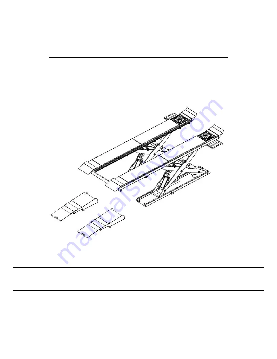
12K SCISSOR LIFT
EELR501A, EELR525A
EELR709A, EELR724A
Nov. 2019 REV.F
309 EXCHANGE AVENUE, CONWAY, ARKANSAS, 72032
TEL: 501-450-1500 FAX: 501-450-1585
EAZ0080V44A
Summary of Contents for EELR501A
Page 6: ...6 of 73 2 0 SAFETY WARNING DECALS...
Page 8: ...8 of 73 Figure 2 Lift Dimensions Side View Figure 3 Lift Dimensions Back View...
Page 18: ...18 of 73 Figure 12 Hydraulic Connections...
Page 33: ...33 of 73 Figure 31 Connection of Air Recoil Hose...
Page 64: ...64 of 73 16 6 Air Line Routing Map Figure 53 Air Hose Assembly...
Page 69: ...69 of 73 17 5 Console Labeling Figure 57 Console Labeling...


