


3-3
CHAPTER 3 Installation
1-2
Installation base
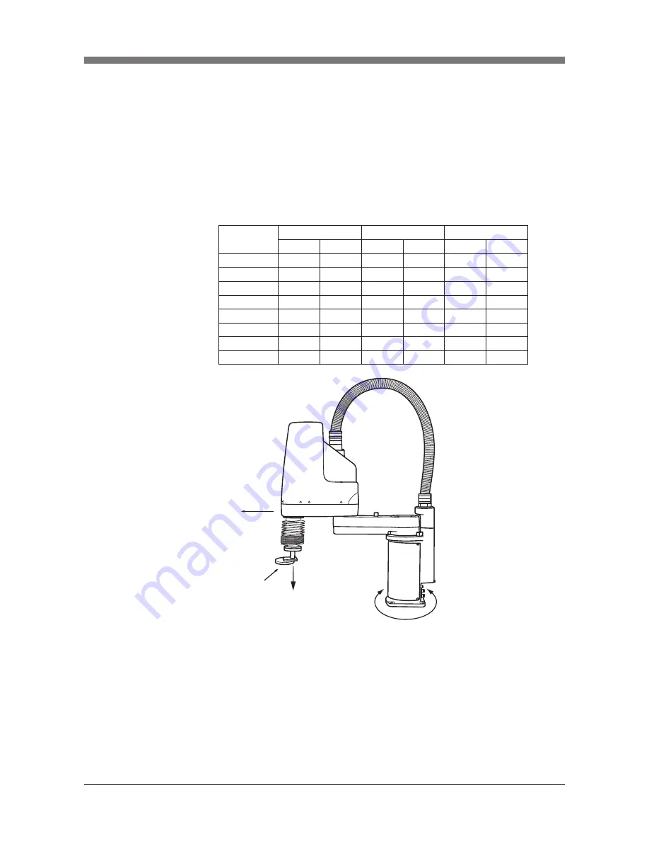
1) Prepare a sufficiently rigid and stable installation base, taking account of
the robot weight including the end effector (gripper), workpiece and reac-
tion force while the robot is operating. The maximum reaction force (see
Fig. 3-1) applied to the X-axis and Z-axis of each robot during operation is
shown in the table below. These values are an instantaneous force applied
to the robot during operation and do not indicate the maximum load capa-
city.
The maximum reaction force
Robot Model
R6YXCH250
R6YXCH350
R6YXCH400
R6YXC500
R6YXC600
R6YXC700
R6YXC800
R6YXC1000
N
kgf
Nm
kgfm
N
kgf
305
31
56
6
40
4
330
34
56
6
40
4
391
40
56
6
40
4
708
72
137
14
89
9
735
75
137
14
89
9
1653
169
304
31
159
16
1707
174
304
31
159
16
1618
165
333
34
127
13
F
X
max
M
X
max
F
Z
max
Fig. 3.1 Maximum reaction force applied during operation
2) The parallelism of the installation base surface must be machined within
a precision of ±0.05mm/500mm. The robot base mount must be installed
facing down and in a level position (except ceiling-mount models which
should be installed with the base mount facing up).
3) Tap holes into the surface of the installation base. For machining dimen-
sions and positions, refer to the dimensional outlines listed in our robot
catalog.
Fxmax
Fzmax
Mxmax
Load
Summary of Contents for SCARA R6Y-XC Series
Page 2: ......
Page 10: ......
Page 12: ......
Page 29: ...CHAPTER 2 Functions 1 Robot Manipulator 2 1 2 Robot Controller 2 5...
Page 30: ......
Page 36: ......
Page 38: ......
Page 51: ...3 13 CHAPTER 3 Installation Fig 3 7 Ground terminal M4 Ground terminal Ground symbol...
Page 104: ......
Page 128: ......
Page 190: ......
Page 192: ......