


4-4
CHAPTER 4 Adjustment
9) Adjust the distance (L) between the Z-axis mechanical stopper and the axis
end so it is set to the value shown in Table 4-1. Then tighten the four bolts
to reassemble the Z-axis motor. (See Fig. 4-4.) At this point, do not allow
the spline shaft position to shift from the correct height.
10) After reassembling the Z-axis motor, adjust the timing belt tension.
To adjust the timing belt tension, see "8 Adjusting the Timing Belt Tension"
in Chapter 4.
11) Reattach the Y-axis upper cover and under cover (R6YXC500 to
R6YXC1000).
To attach the covers, see "7 Removing the Robot Covers" in Chapter 4.
12) Go outside the safeguard enclosure.
13) Check that no one is inside the safeguard enclosure, and then turn on the
controller.
14) Perform the Z-axis absolute reset.
To perform the Z-axis absolute reset, see "3-3 Absolute reset procedures"
in Chapter 4.
After absolute reset is complete, use the following procedure to check if the
adjustment machine reference value
is within the tolerance range (26 and
74).
1- Press the MODE key.
2- Press the F3 key to set MANUAL mode.
3- Press the F13 (LOWER+F3) key to select "RST. ABS ".
4- After the Z-axis absolute reset is complete, press the F10 (UPPER+F5) to
display the
adjustment machine reference value (%)
.
If
adjustment machine reference value
is outside the absolute reset tolerance
range (26 to 74), remove the Z-axis motor again and make fine-adjustment to
the spline shaft height, so that the
adjustment machine reference value
is
within the absolute reset tolerance range.
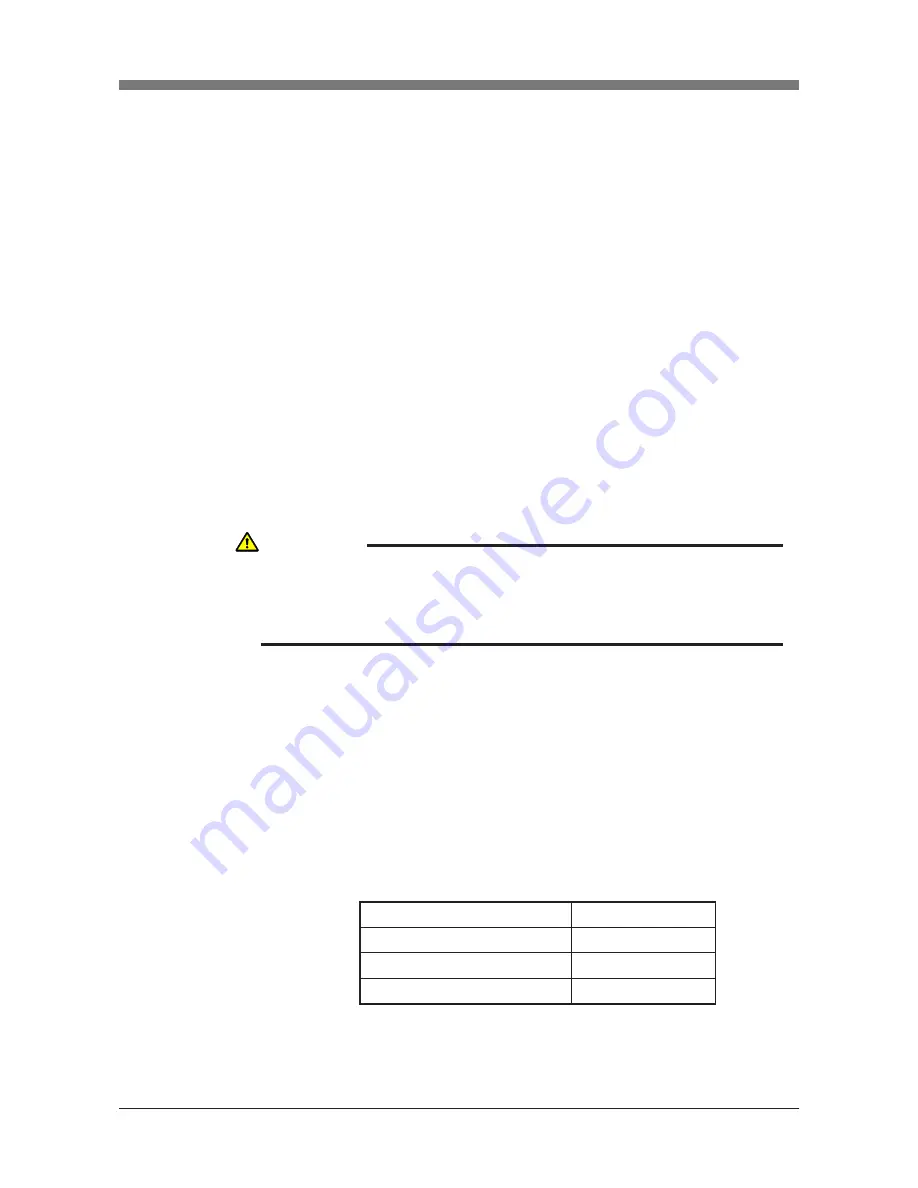
Robot Model
R6YXCH250, R6YXCH350, R6YXCH400
R6YXC500, R6YXC600
L
8mm
8mm
R6YXC700, R6YXC800, R6YXC1000
4mm
Table 4-1
CAUTION
THE ADJUSTMENT MACHINE REFERENCE VALUE IS DISPLAYED WITH
THE PROCEDURE BELOW.
ALWAYS CHECK THE ADJUSTMENT MACHINE REFERENCE VALUE
WHEN THE MACHINE REFERENCE IS ADJUSTED.
Summary of Contents for SCARA R6Y-XC Series
Page 2: ......
Page 10: ......
Page 12: ......
Page 29: ...CHAPTER 2 Functions 1 Robot Manipulator 2 1 2 Robot Controller 2 5...
Page 30: ......
Page 36: ......
Page 38: ......
Page 51: ...3 13 CHAPTER 3 Installation Fig 3 7 Ground terminal M4 Ground terminal Ground symbol...
Page 104: ......
Page 128: ......
Page 190: ......
Page 192: ......