


84
System Maintenance
Section 3-10
Note
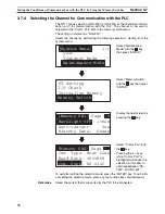
The NT11 uses the same connector for connection to the support tool to the
PLC. If this cable is connected to equipment other than the personal computer
running the support tool, disconnect it from this equipment and connect it to
the support tool before starting the communications check.
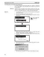
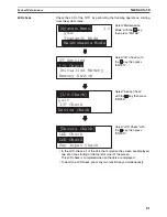
3-10-2 PT Setting Check
Display the settings of the NT11 on the screen by performing the following
operations, starting from the system menu.
• The current settings of the NT11 are displayed.
• To quit the PT setting display, press any two function keys simultaneously.
Quit
Transmit Mode
Maintenance Mode
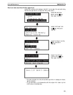
[System Menu]
1.0
PT Setting
I/O Check
Initialize Memory
Memory Switch
Control Area
DM 00000
Notify Area
DM 00010
Select “Maintenance
Mode” with the
key,
then press “ENTER”.
Press “ENTER”.
Summary of Contents for NT11 - 01-2004
Page 1: ...USER S MANUAL Cat No V084 E1 01 NT11 Programmable Terminal ...
Page 2: ...NT11 Programmable Terminal User s Manual Produced January 2004 ...
Page 3: ...iv ...
Page 5: ...vi ...
Page 13: ...xiv Safety Precautions 3 ...
Page 27: ...14 Before Operating Section 1 6 ...
Page 71: ...58 Connecting a Printer Section 2 8 ...
Page 119: ...106 Daily Report Display History Printing Function Section 4 10 ...
Page 157: ...144 Inspection and Cleaning Section 6 3 ...
Page 162: ...149 Appendix B Dimensions Body NT11 SF121 B EV1 38 2 7 5 218 203 113 98 ...
Page 163: ...150 Dimensions Appendix B ...
Page 165: ...152 Transporting and Storing the NT11 Appendix C ...
Page 183: ...170 Revision History ...
Page 186: ...NT11 Programmable Terminal Cat No V084 E1 01 USER S MANUAL ...


