


28
Connection to a PLC by the Host Link (RS-232C Type)
Section 2-4
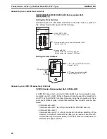
Connecting to a C-series Host Link Unit
C200H/C200HS/C200HE/HG/HX (-Z)E Rack-mounted Unit:
C200H-LK201-V1
Setting the Front Switches
Set each switch with a flat blade screwdriver so that the values or symbols in
the setting value window agree with the following.
Setting the Rear Switches
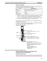
Connecting to a CVM1/CV-series Host Link Unit
CVM1/CV-series Rack-mounted Unit: CV500-LK201
A CVM1/CV-series Host Link Unit (CV500-LK201) has two connectors (com-
munication ports 1 and 2). Either of these ports can be used for connection to
an NT11 by the RS-232C method. However, since the connectors at these
ports are of different types, a cable that matches the connector must be pre-
pared.
• Communication port 1
Communication port 1 is a 25-pin connector for RS-232C use only.
• Communication port 2
Communication port 2 is a 9-pin connector that allows selection of the
RS-232C or RS-422A method. When this port is used with the RS-232C
method, the I/O port selector switch on the front of the Unit must be set to
RS-232C (the upper position).
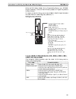
LK201
RUN
RCV
XMT
ERROR
SW1
0
0
5
2
•
Unit # (SW1, SW2)
Set these switches to 0.
•
Command level, parity, and transfer code (SW4)
Set this switch to 2.
•
Baud rate (SW3)
Set this switch to 5 to select 9,600 bps.
Set this switch to 6 to select 19,200 bps.
SW3
SW2
SW4
ON
1
CTS selector switch
External
0 V (ON)
•
1-to-1/1-to-N selection (DIP switch)
Set pin 3 to ON.
•
CTS selection (selector switch)
Set this always to 0 V (ON).
2
3
4
Summary of Contents for NT11 - 01-2004
Page 1: ...USER S MANUAL Cat No V084 E1 01 NT11 Programmable Terminal ...
Page 2: ...NT11 Programmable Terminal User s Manual Produced January 2004 ...
Page 3: ...iv ...
Page 5: ...vi ...
Page 13: ...xiv Safety Precautions 3 ...
Page 27: ...14 Before Operating Section 1 6 ...
Page 71: ...58 Connecting a Printer Section 2 8 ...
Page 119: ...106 Daily Report Display History Printing Function Section 4 10 ...
Page 157: ...144 Inspection and Cleaning Section 6 3 ...
Page 162: ...149 Appendix B Dimensions Body NT11 SF121 B EV1 38 2 7 5 218 203 113 98 ...
Page 163: ...150 Dimensions Appendix B ...
Page 165: ...152 Transporting and Storing the NT11 Appendix C ...
Page 183: ...170 Revision History ...
Page 186: ...NT11 Programmable Terminal Cat No V084 E1 01 USER S MANUAL ...


