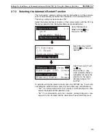


89
Areas for Control/Notification
Section 4-3
4-3
Areas for Control/Notification
This section describes the basics for operating the NT11 through communica-
tions with the PLC using the host link/NT link.
4-3-1
Allocatable Bits and Words
The following bits and words are allocated to the PLC and used for the NT11
operation. The range of respective area varies with the type of PLC.
The allocations must be made without exceeding respective area range.
[OMRON PLCs]
Words Allocated for the PT Status Control Area
Words can be allocated for the PT status control area (host
«
PT) in the fol-
lowing host (PLC) areas.
*1 LR 00000 to LR 00199 are converted to CIO 01000 to CIO 01199.
*2 The EM Area is supported only by the C200HX/HG/HE(-Z)E PLCs.
The Auxiliary Area of the CVM1 and CV-series PLCs is allocated to system
functions, and cannot be used for purposes other than system use.
The range of each memory area differs according to the PLC.
4-3-2
Data Exchange in the Host Link/NT Link
There are two main methods for data exchange when using the host link/NT
link, as follows:
• Using the PT status control area/PT status notify area
• Allocating numeral memory table entries/character string memory table
entries
Symbol
C-series PLCs
Allocation
CV-series PLCs
Allocation
CS/CJ-series PLCs
Allocation
None
IR Area
OK
CIO Area
OK
CIO Area
OK
H
HR Area
OK
---
---
HR Area
Not for Host
Link
A
AR Area
OK
Auxiliary Area
No
AR Area
OK
L
LR Area
OK
---
---
LR Area
*1
Not for Host
Link
T
TC Area,
Timer PVs
No
Timer Area,
Timer PVs
No
TC Area,
Timer PVs
No
TU
---
---
---
---
TC area,
Timer Completion Flags
No
C
TC Area,
Counter PVs
No
Counter Area,
Counter PVs
No
TC Area,
Counter PVs
No
CU
---
---
---
---
TC Area,
Counter Completion Flags
No
W
---
---
---
---
WR Area
Not for Host
Link
TK
---
---
---
---
Task Flags
No
D
DM Area
OK
DM Area
OK
DM Area
OK
E
EM Area
*2
,
current bank
OK
EM Area,
current bank
Not for Host
Link
EM Area,
current bank
Not for Host
Link
E0_ to
EC_
---
---
---
---
EM Area,
EM banks 0 to C
Not for Host
Link
Summary of Contents for NT11 - 01-2004
Page 1: ...USER S MANUAL Cat No V084 E1 01 NT11 Programmable Terminal ...
Page 2: ...NT11 Programmable Terminal User s Manual Produced January 2004 ...
Page 3: ...iv ...
Page 5: ...vi ...
Page 13: ...xiv Safety Precautions 3 ...
Page 27: ...14 Before Operating Section 1 6 ...
Page 71: ...58 Connecting a Printer Section 2 8 ...
Page 119: ...106 Daily Report Display History Printing Function Section 4 10 ...
Page 157: ...144 Inspection and Cleaning Section 6 3 ...
Page 162: ...149 Appendix B Dimensions Body NT11 SF121 B EV1 38 2 7 5 218 203 113 98 ...
Page 163: ...150 Dimensions Appendix B ...
Page 165: ...152 Transporting and Storing the NT11 Appendix C ...
Page 183: ...170 Revision History ...
Page 186: ...NT11 Programmable Terminal Cat No V084 E1 01 USER S MANUAL ...


