


56
Connection to a PLC by the NT Link (RS-422A Type)
Section 2-7
The 1:1 NT Link method cannot be used using RS-485. To use the 1:1 NT
Link method, connect by RS-422A.
NT link connection using RS-422A/485 is not possible with the CPM1,
CPM2A, and CPM2C.
Settings at the Host
The setting methods for each model of Unit are described below.
• Connecting to a CVM1/CV-series (-EV
@
) CPU Units
CVM1-CPU01-EV2/CVM1-CPU11-EV2/CVM1-CPU21-EV2
PLC Setup
When connecting to the CVM1/CV-series CPU Unit by the 1:1 NT Link
method, no particular settings are required at the PLC Setup.
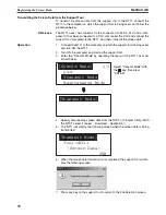
Setting the Front Switches
Connecting to a C-series C200HX/HG/HE(-Z)E or CQM1H
PLC Setup Settings
Write the PLC Setup (data memory) settings directly from a Programming
Device (e.g., CX-Programmer) in accordance with the host model.
*1 RS-422A port of the Serial Communications Board
*2 RS-422A port of the Serial Communications Board
For details on operations relating to the PLC Setup, refer to the manual for the
PLC you are using.
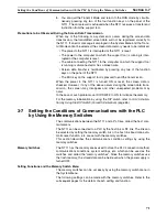
Setting the DIP Switches on a C200HX/HG/HE(-Z)E Serial
Communications Board
Set the switches on a C200HX/HG/HE(-Z)E Serial Communications Board as
follows.
Switch 1: Set to 4 (4-wire, for RS-422A)
Switch 2: Set to ON for terminator ON (terminating resistance applied)
Host Model
Word
Writing Value
Setting
Port A of C200HX/HG/HE(-Z)E
*1
DM6555
4000
Use 1:1 NT Link
Port 2 of CQM1H
*2
DM6550
4000
•
Host Link communication method selection
(selector switch)
Set this to RS-422A.
•
Terminator setting (pin 6)
Set this switch to ON.
(Set terminator ON.)
I/O port selector switch
RS-422A
RS-232C
•
Communications type setting (pin 3)
Set this switch to ON.
(for communication by NT link)
Summary of Contents for NT11 - 01-2004
Page 1: ...USER S MANUAL Cat No V084 E1 01 NT11 Programmable Terminal ...
Page 2: ...NT11 Programmable Terminal User s Manual Produced January 2004 ...
Page 3: ...iv ...
Page 5: ...vi ...
Page 13: ...xiv Safety Precautions 3 ...
Page 27: ...14 Before Operating Section 1 6 ...
Page 71: ...58 Connecting a Printer Section 2 8 ...
Page 119: ...106 Daily Report Display History Printing Function Section 4 10 ...
Page 157: ...144 Inspection and Cleaning Section 6 3 ...
Page 162: ...149 Appendix B Dimensions Body NT11 SF121 B EV1 38 2 7 5 218 203 113 98 ...
Page 163: ...150 Dimensions Appendix B ...
Page 165: ...152 Transporting and Storing the NT11 Appendix C ...
Page 183: ...170 Revision History ...
Page 186: ...NT11 Programmable Terminal Cat No V084 E1 01 USER S MANUAL ...


