


31
Connection to a PLC by the Host Link (RS-232C Type)
Section 2-4
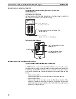
Either set PLC Setup directly from a Programming Device (e.g., SYSMAC
Support Software), or transmit the PLC Setup made at a Programming Device
to the CPU Unit.
For details on the PLC Setup, refer to the
SYSMAC CVM1/CV500/1000/2000
Operation Manual: Ladder Diagrams
(W202-E1-
@
).
Setting the Front Switches
C-series C200HS, C200HX/HG/HE(-Z)E, CPM1, CPM2A, CPM2C, CQM1,
CQM1H CPU Units and SRM1
The connection method depends upon the model of PLC being used, as
shown in the following table.
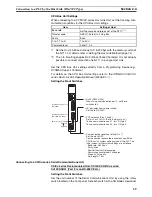
PLC model
Connection method
C200HS, CQM1
Connect to the CPU Unit’s built-in RS-232C port.
C200HX/HG/HE(-Z)E
• Connect to the CPU Unit’s built-in RS-232C port.
• Connect to one of the RS-232C ports (port A or port B) on
a Serial Communications Board.
CQM1H
• Connect to the CPU Unit’s built-in RS-232C port.
• Connect to the peripheral port through a CS1W-CN118
Connecting Cable.
• Connect to the RS-232C port (port 1) on a Serial Commu-
nications Board.
CPM1
Connect to the peripheral port through a CPM1-CIF01 RS-
232C Adapter.
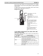
RS-232C
I/O port selector switch
RS-422A
•
Host Link Communication method
•
System setting (Pin 4)
- DIP switch settings:
- PLC Setup:
(selector switch)
Set this to RS-232C.
To effect the existing DIP switch settings,
set SW4 to ON.
To effect the existing PLC Setup, set pin 4
to OFF.
Note
For CPU Units manufactured before or
during June 1995 (lot No.
@@
65), the
existing DIP switch settings differ from
the existing PLC Setup as follows.
2,400 bps, 1 stop bit, even parity, 7 bit
data length
9,600 bps, 2 stop bits, even parity, 7 bit
data length
For CPU Units manufactured from July
1995 onward (lot No.
@@
75), the
stipulated values in the DIP switch
settings also are 9,600 bps and 2 stop
bits.
Summary of Contents for NT11 - 01-2004
Page 1: ...USER S MANUAL Cat No V084 E1 01 NT11 Programmable Terminal ...
Page 2: ...NT11 Programmable Terminal User s Manual Produced January 2004 ...
Page 3: ...iv ...
Page 5: ...vi ...
Page 13: ...xiv Safety Precautions 3 ...
Page 27: ...14 Before Operating Section 1 6 ...
Page 71: ...58 Connecting a Printer Section 2 8 ...
Page 119: ...106 Daily Report Display History Printing Function Section 4 10 ...
Page 157: ...144 Inspection and Cleaning Section 6 3 ...
Page 162: ...149 Appendix B Dimensions Body NT11 SF121 B EV1 38 2 7 5 218 203 113 98 ...
Page 163: ...150 Dimensions Appendix B ...
Page 165: ...152 Transporting and Storing the NT11 Appendix C ...
Page 183: ...170 Revision History ...
Page 186: ...NT11 Programmable Terminal Cat No V084 E1 01 USER S MANUAL ...


