


122
Memory Table Entries and Bar Graph
Section 5-3
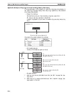
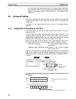
Write a memory table entry number etc. to the copy memory table setting
area in the PT status control area in the PLC memory. Data will be copied
between the memory table entries in the NT11 and the displayed value will
change accordingly.
Reference
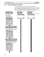
This procedure is convenient to switch predetermined values or character-
strings according to the situation. By preparing several units of contents, vari-
ous contents can be displayed by switching them to suit the situation.
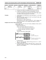
[“Copy memory table setting” of the PT status control area]
Copy type:
0: Copy between the character-string memory table entries
1: Copy between the numeral memory table entries
Copy source and destination memory table entry numbers:
Character-string memory table: 000 to 128
Numeral memory table: 000 to 128
• Available allocation words
The PT status control area can be allocated to the following PLC areas:
Words Allocated for the PT Status Control Area
Words can be allocated for the PT status control area (host
«
PT) in the fol-
lowing host (PLC) areas.
NT11
PLC
Memory
table copy
source
Copy
destination (for
display)
PT status control area
Screen switch setting
PT status control setting
Copy source
number
Copy destination
number
A
A
A
Copy memory
table setting
15 14 13 12 11 10 9 8 7 6 5 4 3 2 1 0 Bit
Word
n+1
Copy memory
table setting
n+2
0
Copy source memory table No. (3-digit BCD)
Copy type
Copy destination memory table No. (3-digit BCD)
Symbol
C-series PLCs
Allocation
CV-series PLCs
Allocation
CS/CJ-series PLCs
Allocation
None
IR Area
OK
CIO Area
OK
CIO Area
OK
H
HR Area
OK
---
---
HR Area
Not for Host
Link
A
AR Area
OK
Auxiliary Area
No
AR Area
OK
L
LR Area
OK
---
---
LR Area
*1
Not for Host
Link
T
TC Area,
Timer PVs
No
Timer Area,
Timer PVs
No
TC Area,
Timer PVs
No
TU
---
---
---
---
TC area,
Timer Completion Flags
No
C
TC Area,
Counter PVs
No
Counter Area,
Counter PVs
No
TC Area,
Counter PVs
No
CU
---
---
---
---
TC Area,
Counter Completion Flags
No
W
---
---
---
---
WR Area
Not for Host
Link
TK
---
---
---
---
Task Flags
No
D
DM Area
OK
DM Area
OK
DM Area
OK
Summary of Contents for NT11 - 01-2004
Page 1: ...USER S MANUAL Cat No V084 E1 01 NT11 Programmable Terminal ...
Page 2: ...NT11 Programmable Terminal User s Manual Produced January 2004 ...
Page 3: ...iv ...
Page 5: ...vi ...
Page 13: ...xiv Safety Precautions 3 ...
Page 27: ...14 Before Operating Section 1 6 ...
Page 71: ...58 Connecting a Printer Section 2 8 ...
Page 119: ...106 Daily Report Display History Printing Function Section 4 10 ...
Page 157: ...144 Inspection and Cleaning Section 6 3 ...
Page 162: ...149 Appendix B Dimensions Body NT11 SF121 B EV1 38 2 7 5 218 203 113 98 ...
Page 163: ...150 Dimensions Appendix B ...
Page 165: ...152 Transporting and Storing the NT11 Appendix C ...
Page 183: ...170 Revision History ...
Page 186: ...NT11 Programmable Terminal Cat No V084 E1 01 USER S MANUAL ...


