


26
Connection to a PLC by the Host Link (RS-232C Type)
Section 2-4
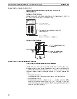
CVM1/CV-series Host Link Units (CV500-LK201) have two types of connec-
tor; a 25-pin connector (communication port 1), and a 9-pin connector (com-
munication port 2). When using communication port 2, refer to
Wiring for
Other Connections (Other Than the Memory Link Method)
(page 26).
* For Units that have a CTS setting selector switch, RS and CS do not have to
be shorted if this switch is set to 0 V.
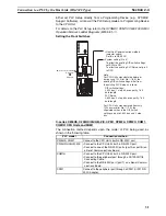
Wiring for Other
Connections
Applicable Units:
CV500-LK201 (communication port 2)
CS1W-SCU21
CJ1W-SCU41
CPM1-10CDR-
@
CPM1-20CDR-
@
CPM1-30CDR-
@
CPM1A-10CD
@
-
@
CPM1A-20CD
@
-
@
CPM1A-30CD
@
-
@
CPM1A-40CD
@
-
@
CPM2A-30CD
@
-
@
CPM2A-40CD
@
-
@
CPM2A-60CD
@
-
@
CPM2C-10
@@@@@@
-
@
CPM2C-20
@@@@@@
-
@
CQM1-CPU21-E
CQM1-CPU41-EV1
CQM1-CPU42-EV1
CQM1-CPU43-EV1
CQM1-CPU44-EV1
CQM1H-CPU11
CQM1H-CPU21
CQM1H-CPU51
CQM1H-CPU61
CS1G-CPU42-E(V1)
CS1G-CPU43-E(V1)
CS1G-CPU44-E(V1)
CS1G-CPU45-E(V1)
CS1H-CPU63-E(V1)
CS1H-CPU64-E(V1)
CS1H-CPU65-E(V1)
CS1H-CPU66-E(V1)
CS1H-CPU67-E(V1)
CS1G-CPU42H
CS1G-CPU43H
CS1G-CPU44H
CS1G-CPU45H
CS1H-CPU63H
CS1H-CPU64H
CS1H-CPU65H
CS1H-CPU66H
CS1HCPU67H
CJ1G-CPU44
CJ1G-CPU45
C200HS-CPU21-E, -EC C200HS-CPU23-E
C200HS-CPU31-E
C200HS-CPU33-E
C200HE-CPU32-(Z)E
C200HE-CPU42-(Z)E
C200HG-CPU33-(Z)E
C200HG-CPU43-(Z)E
C200HG-CPU53-(Z)E
C200HG-CPU63-(Z)E
C200HX-CPU34-(Z)E
C200HX-CPU44-(Z)E
1
6
5
9
*
NT11
1
14
13
25
FG
+5V
CS
RS
RD
SD
5G
1
2
3
4
5
6
7
8
9
2
3
4
5
6
7
8
-
-
-
-
FG
5G
CS
RS
RD
SD
ER
-
-
-
-
-
PLC (Host Link Unit)
(25-pin type)
(9-pin type)
RS-232C
interface
RS-232C
interface
Abbreviation
Pin
number
Abbreviation
Pin
number
Connector
hood
Shield
Connector
hood
Summary of Contents for NT11 - 01-2004
Page 1: ...USER S MANUAL Cat No V084 E1 01 NT11 Programmable Terminal ...
Page 2: ...NT11 Programmable Terminal User s Manual Produced January 2004 ...
Page 3: ...iv ...
Page 5: ...vi ...
Page 13: ...xiv Safety Precautions 3 ...
Page 27: ...14 Before Operating Section 1 6 ...
Page 71: ...58 Connecting a Printer Section 2 8 ...
Page 119: ...106 Daily Report Display History Printing Function Section 4 10 ...
Page 157: ...144 Inspection and Cleaning Section 6 3 ...
Page 162: ...149 Appendix B Dimensions Body NT11 SF121 B EV1 38 2 7 5 218 203 113 98 ...
Page 163: ...150 Dimensions Appendix B ...
Page 165: ...152 Transporting and Storing the NT11 Appendix C ...
Page 183: ...170 Revision History ...
Page 186: ...NT11 Programmable Terminal Cat No V084 E1 01 USER S MANUAL ...


