


35
Connection to a PLC by the Host Link (RS-232C Type)
Section 2-4
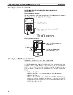
Setting the Switches on an RS-232C Adapter
When using a CPM1-CIF01 RS-232C Adapter, set the mode switch as shown
in the following diagram.
CS/CJ-series CPU Unit model: CS1G/HCPU
@@
-E (-V1)
CS1G/H-CPU
@@
H
CJ1G-CPU
@@
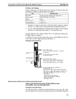
Connect to the built-in RS-232C port of the CPU Unit, or the RS-232C port of
the Communication Board. Note that the connection to a peripheral port must
be made via an RS-232C Adapter (CS1W-CN118) specially designed for con-
necting to a peripheral port.
PLC Setup
When connecting to a CS/CJ-series CPU Unit, set the following communica-
tion conditions for the PLC Setup. Since the settings shown below are the
PLC default settings for the CPU Unit, no change to the PLC Setup is neces-
sary as long as the baud rate is maintained at 9,600 bps.
*1 Set the Host Link baud rate up to 115,200 bps with the memory switch at
the NT11. For details, refer to
Settings the Host Link Method
(page 74).
When the baud rate is set to 19,200 bps, the PLC Setup of the CPU Unit
need to be changed.
Either set the PLC Setup directly from a Programming Device (Programming
Console), or transmit the PLC Setup made at a Programming Device (CX-
Programmer) to the CPU Unit.
The settings for SW1 and SW2 depend upon the usage of the
peripheral port and RS-232C port.
•
Connecting PT to peripheral port
•
Connecting PT to built-in RS-232C port
(A device that requires non-standard communications settings
is connected to the peripheral port.)
SW1: OFF
SW2: ON
•
Connecting PT to built-in RS-232C port
(A Programming Console is connected to the peripheral port.)
SW1: OFF
SW2: OFF
Item
Setting at Host
Baud rate
Set the same speed as set at the NT11
(*1)
Stop bits
2 stop bits
Parity
Even
Data length
ASCII 7 bits
Unit No. for the Host Link
00
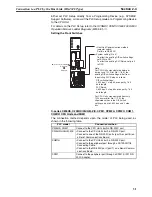
CPM1
Set the mode setting switch to HOST (upper position).
CPM1-
CIF01
Summary of Contents for NT11 - 01-2004
Page 1: ...USER S MANUAL Cat No V084 E1 01 NT11 Programmable Terminal ...
Page 2: ...NT11 Programmable Terminal User s Manual Produced January 2004 ...
Page 3: ...iv ...
Page 5: ...vi ...
Page 13: ...xiv Safety Precautions 3 ...
Page 27: ...14 Before Operating Section 1 6 ...
Page 71: ...58 Connecting a Printer Section 2 8 ...
Page 119: ...106 Daily Report Display History Printing Function Section 4 10 ...
Page 157: ...144 Inspection and Cleaning Section 6 3 ...
Page 162: ...149 Appendix B Dimensions Body NT11 SF121 B EV1 38 2 7 5 218 203 113 98 ...
Page 163: ...150 Dimensions Appendix B ...
Page 165: ...152 Transporting and Storing the NT11 Appendix C ...
Page 183: ...170 Revision History ...
Page 186: ...NT11 Programmable Terminal Cat No V084 E1 01 USER S MANUAL ...


