


130
NT11 Status Control
Section 5-5
Reference
1.
Instead of switching bit 15 ON, a screen number can be specified to switch
to that screen, in which case the screen will be displayed. For details on
screen switching, refer to
5-2-2 Switching the Screen Display
(page 110).
2.
By setting an NT11 memory switch, it is possible to make the backlight go
off automatically after no operations have been performed for a set length
of time.
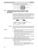
• Display history print (bit 5)
”Display history printing” designates printing of the display history data re-
corded in the NT11 at a printer. When bit 5 is set ON (set to “1”), all the
recorded display history data is printed out once. To print it out a second
time, bit 5 must be switched OFF (set to “0”) and then switched back ON
(to “1”).
Reference
For details on the data recorded in the display history and the printing format,
refer to
4-10 Daily Report/Display History Printing Function
(page 102).
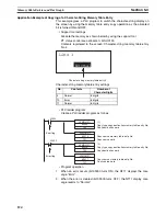
• Daily report print (bit 4)
“Daily report print” designates printing of the contents of PLC words and
set characters in accordance with a format set using the support tool.
When bit 4 is switched ON (set to “1”), the contents of the specified words
are read from the PLC and output to the printer once in the specified for-
mat.
To output the data to the printer again, bit 4 must be switched OFF (set to
“0”) and then switched back ON (to “1”).
Reference
Settings such as the printing format and word settings are made by using the
support tool. For details on the support tool setting procedures relating to the
daily report printing function, refer to
4-10 Daily Report/Display History Print-
ing Function
(page 102).
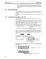
5-5-2
How to Control NT11 Functions
This section describes how to control the functions of the NT11.
• Restrictions on allocating words
The PT status control area (PLC
®
PT) can be allocated to the PLC mem-
ory areas listed in the following table.
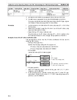
Words Allocated for the PT Status Control Area
Words can be allocated for the PT status control area (host
«
PT) in the fol-
lowing host (PLC) areas.
Symbol
C-series PLCs
Allocation
CV-series PLCs
Allocation
CS/CJ-series PLCs
Allocation
None
IR Area
OK
CIO Area
OK
CIO Area
OK
H
HR Area
OK
---
---
HR Area
Not for Host
Link
A
AR Area
OK
Auxiliary Area
No
AR Area
OK
L
LR Area
OK
---
---
LR Area
*1
Not for Host
Link
T
TC Area,
Timer PVs
No
Timer Area,
Timer PVs
No
TC Area,
Timer PVs
No
TU
---
---
---
---
TC area,
Timer Completion Flags
No
C
TC Area,
Counter PVs
No
Counter Area,
Counter PVs
No
TC Area,
Counter PVs
No
Summary of Contents for NT11 - 01-2004
Page 1: ...USER S MANUAL Cat No V084 E1 01 NT11 Programmable Terminal ...
Page 2: ...NT11 Programmable Terminal User s Manual Produced January 2004 ...
Page 3: ...iv ...
Page 5: ...vi ...
Page 13: ...xiv Safety Precautions 3 ...
Page 27: ...14 Before Operating Section 1 6 ...
Page 71: ...58 Connecting a Printer Section 2 8 ...
Page 119: ...106 Daily Report Display History Printing Function Section 4 10 ...
Page 157: ...144 Inspection and Cleaning Section 6 3 ...
Page 162: ...149 Appendix B Dimensions Body NT11 SF121 B EV1 38 2 7 5 218 203 113 98 ...
Page 163: ...150 Dimensions Appendix B ...
Page 165: ...152 Transporting and Storing the NT11 Appendix C ...
Page 183: ...170 Revision History ...
Page 186: ...NT11 Programmable Terminal Cat No V084 E1 01 USER S MANUAL ...


