background image

3-11

Section

Monitoring

83

3. When there are two or more Masters displayed in the network configuration

and one of the Masters is selected, the communications cycle times of the
selected Master will be monitored.

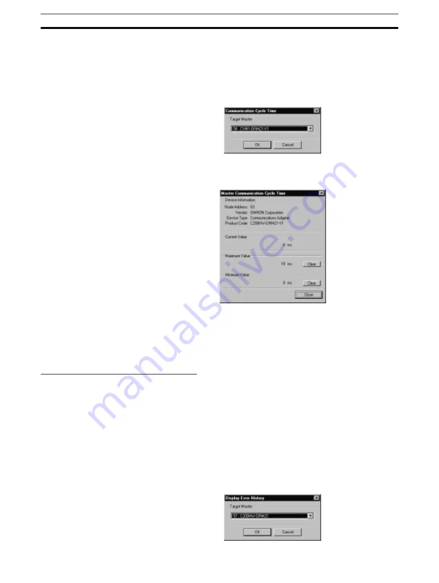
If there isn’t a Master selected, a window will be displayed to specify a Mas-
ter as shown in the following diagram. In this case, specify the desired Mas-
ter and click on “OK” to start monitoring.

The Master Communication Cycle Time window will be displayed.

The maximum or minimum communications cycle time value can be cleared
by clicking on “Clear” next to the corresponding box.

4. To exit the Master Communication Cycle Time monitoring command, click

on “Close” at the bottom of the window.

Displaying the Master’s Error History

The “Display Master Error History” command reads and displays the error his-
tory recorded in OMRON Master Units.

1, 2, 3...

1. Select “Monitor” from the menu bar while online.

2. Select “Display Master Error History” from the Monitor menu.

3. When there are two or more Masters displayed in the network configuration

and one of the Masters is selected, the error history of the selected Master
will be displayed.

If there isn’t a Master selected, a window will be displayed to specify a Mas-
ter as shown in the following diagram. In this case, specify the desired Mas-
ter and click on “OK” to display its error history.

Summary of Contents for 3G8E2-DRM21

Page 1: ...Cat No W328 E1 2 CompoBus D Configurator 3G8F5 DRM21 ISA Board 3G8E2 DRM21 PCMCIA Board OPERATION MANUAL...

Page 2: ......

Page 3: ...3G8F5 DRM21 ISA Board 3G8E2 DRM21 PCMCIA Board CompoBus D Configurator Operation Manual Revised August 1999...

Page 4: ......

Page 5: ...types of information Note Indicates information of particular interest for efficient and convenient operation of the product 1 2 3 1 Indicates lists of one sort or another such as procedures checklist...

Page 6: ......

Page 7: ...Operations Flowchart 48 3 2 Main Window Device List Window 49 3 3 Configurator Display Settings 51 3 4 Switching between Online and Offline 52 3 5 Reading the Network s Configuration 53 3 6 Creating a...

Page 8: ......

Page 9: ...sary hardware settings and personal computer settings and install the CompoBus D Configurator software in the personal computer Section 3 explains how to make the necessary settings with the CompoBus...

Page 10: ......

Page 11: ...reliable application of the CompoBus D Devi ceNet Configurator and personal computer You must read this section and understand the information contained before attempting to set up or operate a Compo...

Page 12: ...ng operation WARNING It is extremely important that a PC and all PC Units be used for the specified purpose and under the specified conditions especially in applications that can directly or indirectl...

Page 13: ...Be particularly careful in places where the power supply is unstable Install external breakers and take other safety measures against short circuit ing in external wiring Do not attempt to disassemble...

Page 14: ......

Page 15: ...es and capabilities of the CompoBus D Configurator 1 1 Introduction 2 1 1 1 Functions of the CompoBus D Configurator 3 1 1 2 Features of the CompoBus D Configurator 8 1 1 3 Configuration Patterns for...

Page 16: ...to 20 mA 1 V to 5 V or 4 mA to 20 mA Switches with Connectors CQM1 Note Use the Remote Adapters in combination with Remote Terminals Settings must be made with the CompoBus D Configurator in the foll...

Page 17: ...he following ferrite cores Company Fair Rite Products Corp Models 0443 164251 045A 164257 Address One Commercial Row Wallkill NY 12589 0288 USA Phone 914 895 2055 Fax 914 895 1974 1 1 1 Functions of t...

Page 18: ...nal computer s files 2 A personal computer becomes a node in the CompoBus D network when the CompoBus D Configurator is installed and an ISA Board or PCMCIA Card is mounted Be sure that the personal c...

Page 19: ...hese Slave param eters can be set by acquiring an EDS file for Slave settings from the manufac turer or reading parameters from a Slave in the network It is also possible to edit Slave parameters and...

Page 20: ...displays the status of the specified OMRON Master Unit The sta tus of Slaves involved in remote I O communications with the Master will also be displayed This function displays the status of the speci...

Page 21: ...ponding EDS file Installing the EDS file allows the CompoBus D Configurator to recognize the other company s Slave and in some cases change the device s Slave parameters When another company s Slave i...

Page 22: ...es can be connected to the CompoBus D network very easily for remote I O communications or message communications When the CompoBus D Configurator is used I O words and node addresses can be allocated...

Page 23: ...er See note 2 The PC s communication cycle time will be longer Precautions Same as earlier networks See the precautions described on page 87 Two Masters can t control the same Slave A Bus Off error ma...

Page 24: ...ses aren t duplicated Observe the following precautions when using the CompoBus D Configurator The only DeviceNet Master Units that can be handled by the CompoBus D Configurator are the OMRON CVM1 DRM...

Page 25: ...er near the card as shown in the following diagram Ferrite core Ferrite cores Note We recommend one of the following ferrite cores Company Fair Rite Products Corp Models 0443 164251 045A 164257 Addres...

Page 26: ......

Page 27: ...tion Procedure 14 2 2 ISA Board Installation 14 2 2 1 Preparation for Installation 14 2 2 2 ISA Board Components and Functions 17 2 2 3 DIP Switch Settings 17 2 2 4 Installation in the Computer 18 2 3...

Page 28: ...scription Unused expansion slot Verify that there is an unused expansion slot ISA slot in the computer Available memory The ISA board for the Configurator occupies 16 KB of memory between memory addre...

Page 29: ...D3FF DEVICE C WINDOWS EMM386 EXE 1 2 3 1 Click on the Start button and select Control Panel from the Settings menu 2 Double click on the System icon in the Control Panel window 3 Select Device Manage...

Page 30: ...ting Input output O from the Reserve Resources window click on Add and register the range of I O port addresses for the ISA Board as shown in the following diagram In this example I O port addresses 2...

Page 31: ...gurator s ISA Board and their functions ISA Bus Connector Connect to the computer s ISA slot DIP Switch Sets the I O port address which the ISA Board will use CompoBus D Communications Connector Conne...

Page 32: ...0 1 0 1 0 2A8 to 2AF 1 0 1 0 1 0 2B0 to 2B7 0 1 1 0 1 0 2B8 to 2BF 1 1 1 0 1 0 2C0 to 2C7 0 0 0 1 1 0 2C8 to 2CF 1 0 0 1 1 0 2D0 to 2D7 0 1 0 1 1 0 2D8 to 2DF 1 1 0 1 1 0 2E0 to 2E7 0 0 1 1 1 0 2E8 t...

Page 33: ...that the computer has 16 KB of available memory Use one of the memory and I O port address combinations shown on page 21 for the PCMCIA Card Unused I O port address The PCMCIA card for the Configurat...

Page 34: ...y Resources at the top of the window 6 When Input output O is selected from the Resource Display the current I O port allocations will be displayed 7 Repeat step 6 to verify the status of the memory a...

Page 35: ...CFFFFH 9 280H D0000 to D3FFFH 10 D4000 to D7FFFH 11 C8000 to CBFFFH 12 CC000 to CFFFFH 13 288H D0000 to D3FFFH 14 D4000 to D7FFFH 15 C8000 to CBFFFH 16 CC000 to CFFFFH 2 3 2 PCMCIA Card Components and...

Page 36: ...ator Version 1 12 or earlier page 31 Setup procedure for OSR2 Windows 95 with CompoBus D Configurator Ver sion 1 12 or earlier page 36 Note 1 The operations and screen displays may differ slightly dep...

Page 37: ...rocedure remove any PCMCIA Cards including those for the CompoBus D Configurator that are currently being used Since the PCMCIA Card can t be used temporarily during the setup it may not be pos sible...

Page 38: ...isk is still in the floppy disk drive before starting this step 4 Select Floppy disk drives as the driver location to be searched then click on Next 5 The driver file will be recognized as shown below...

Page 39: ...click on to the left of SST Devices to check that x or is not displayed at PCMCIA Card driver 5136 DN PCM n where n is the PCMCIA slot num ber 2 Verify the resources currently being used as follows Do...

Page 40: ...etup 1 2 3 1 Insert the PCMCIA Card installation disk provided into the floppy disk drive 2 Install the PCMCIA Card when the Windows system is active The PCMCIA Card will be recognized as new hardware...

Page 41: ...been added then click on to the left of SST Devices to check that x or is not displayed at PCMCIA Card driver 5136 DN PCM n where n is the PCMCIA slot num ber 2 Verify the resources currently being us...

Page 42: ...1 Insert the PCMCIA Card installation disk provided into the floppy disk drive 2 Install the PCMCIA Card when the Windows system is active The PCMCIA Card will be recognized as new hardware and the Up...

Page 43: ...iver Resources 1 2 3 1 After Windows 95 is restarted check that the driver has been installed cor rectly as follows Click on the Start button select Control Panel from the Settings menu double click o...

Page 44: ...n Prop erties window and select the Resources tab from the top of the window The automatically set Input Output Range and Memory Range values will be displayed This completes installation of the PCMC...

Page 45: ...procedure remove any PCMCIA Cards including those for the CompoBus D Configurator that are currently being used Since the PCMCIA Card can t be used temporarily during the setup it may not be pos sibl...

Page 46: ...nstallation 32 5 Select No to disable the automatic hardware detection function then click on Next 6 Select Other devices as the type of hardware to be installed then click on Next 7 Click on Have Dis...

Page 47: ...ed in step 1 then click on OK Normally the floppy disk drive is drive A Note Make sure that the PCMCIA Card installation disk is still in the floppy disk drive before starting this step 9 Select Omron...

Page 48: ...n the System icon in the Control Panel window and select the Device Manager tab from the top of the System Proper ties window refer to page 19 b Click on to the left of PCMCIA socket to display the dr...

Page 49: ...s been added then click on to the left of SST Devices to check that x or is not displayed at PCMCIA Card driver 5136 DN PCM n where n is the PCMCIA slot num ber 2 Verify the resources currently being...

Page 50: ...This driver must be replaced with a dedicated driver Before starting the setup procedure remove any PCMCIA Cards including those for the CompoBus D Configurator that are currently being used Since th...

Page 51: ...ab from the top of the window and click on Update Driver 5 Select Yes Recommended to enable the automatic hardware detection function then click on Next 6 Select Original driver Recommended as the dri...

Page 52: ...r asking the user to insert the PCMCIA Card installation disk Since the floppy disk has already been inserted in step 1 just click on OK The driver will be installed The following window will be displ...

Page 53: ...iver has been installed correctly as follows Click on the Start button select Control Panel from the Settings menu double click on the System icon in the Control Panel window and select the Device Man...

Page 54: ...as the installation procedure 2 4 CompoBus D Configurator Installation This section explains how to install the CompoBus D Configurator The Configu rator is installed by executing the Configurator s...

Page 55: ...ogram For Windows NT 3 51 select Run from the File menu 4 Specify A setup exe for the command line and click on OK It is also possible to click on Browse and select the setup exe file from the A drive...

Page 56: ...ware will create it automatically 8 Specify the name of the Windows program folder where the Configurator icons will be registered An OMRON folder will be created in the specified folder and the Confi...

Page 57: ...ISA Board or PCMCIA Card Note The setup for the ISA Board or PCMCIA Card can be performed later by running the 3G8xx DRM21 Configuration program that is in the same program folder as the CompoBus D C...

Page 58: ...run immediately Click on OK to start the Configurator With Windows NT a popup window will be displayed asking whether or not to restart Windows 18 This completes installation of the CompoBus D Config...

Page 59: ...Bus D Communications Connector as shown in the following diagram 2 6 Controlling the CompoBus D Configurator After installing the CompoBus D Configurator verify that the Configurator can be started 1...

Page 60: ...ll operate normally if the Configurator has the following settings when Online is selected from the File menu CompoBus D Cable connected Online normally CompoBus D Cable disconnected Bus off The statu...

Page 61: ...g Editing Master Parameters 56 3 6 3 Creating Master Parameters Independently 58 3 6 4 Creating Master Parameters with the Wizard 67 3 6 5 Editing Master Parameters 73 3 6 6 Creating Editing Slave Par...

Page 62: ...and PC Register delete Slaves as necessary I O Allocation Automatically allocated by the wizard Write the data to the Master parameter file Create Master parameters or use the Master param eter wizard...

Page 63: ...con The tool bar icons correspond to the following menu commands Open Save Device list Stop displaying device list Edit device parameters Monitor status Display error history Online Offline The size o...

Page 64: ...status Num Lock status Scroll Lock status Note When a bus off error occurs go offline momentarily and then go online again Device Icons in the Device List A different icon is displayed for each type...

Page 65: ...d by holding the left button of the mouse on a boundary line between two columns and moving the mouse The width of the node address column can t be changed If you double click on the boundary line at...

Page 66: ...ations Note 1 The setting for the listing order is stored in memory so the last setting will be used the next time the Configurator is started 2 One Master can engage in FINS message service communica...

Page 67: ...e displayed in blue in the network connection status area on the bottom line of the Configurator window An error message will be displayed if communications could not be estab lished with the network...

Page 68: ...ompoBus D network and updates the device list display based on that information Information will be read from the devices in node address order regardless of the display order format specified for the...

Page 69: ...s created offline Switch to online after writing the file specify the Master Unit in the device list read the file and write the file to the device Parameters created online When the Master Unit is sp...

Page 70: ...ettings Master Master Unit information Master Unit model and model of the PC to which the Master is mounted Register Slave Registration of the Slaves participating in remote I O communications Node ad...

Page 71: ...ile saved from a device list of the actual network This method can be used to edit Master parameters created when it isn t possible to connect directly to the network or to change the parameters for a...

Page 72: ...s Independently Setting Displaying the Master and PC Model 1 2 3 1 Select Create Master Parameters from the File menu The following win dow will be displayed 2 Select the model Unit of the Master Unit...

Page 73: ...a Slave is registered here it isn t necessary to input the number of I O bytes occupied by the Slave when doing the I O allocation b The width of the columns in the registered Slave display area can...

Page 74: ...e manufacturer s vendor code manually A Slave can t be registered with a vendor code of 0 iii Select the device type in the right column of Device Type input area The corresponding code will appear au...

Page 75: ...e display area can be adjusted just like the width of the columns in the device list display area The order in which the Slaves are listed can be changed too To change the listing order click on the h...

Page 76: ...s will stop and it will not be possible to start them from either the software switches or the CompoBus D Configurator 3 To set the starting word address and number of words for each block click on th...

Page 77: ...are 4 ways to display the Slave s I O allocation window Any of these methods can be used Displaying a Slave s I O Allocation Window 1 Double click on the desired Slave 2 Select the desired Slave and...

Page 78: ...lock 2 458 words Allocated word Bytes occupied 1 byte 4 bytes When remote I O communications aren t being carried out with the Slave just explicit message communications click on the box next to Expli...

Page 79: ...the bottom of the column iii Release the left mouse button over the High or Low byte in the desired word The required number of bytes will be allocated to the Slave starting with that byte When the Sl...

Page 80: ...work condi tions can be avoided Setting a long communications cycle time can prevent errors that occur because of Slaves that are very slow When the actual remote I O communications time is shorter th...

Page 81: ...information Ending the Create Master Parameters Process 1 2 3 1 Click on Close in the bottom right corner of the window A confirmation window will be displayed 2 Click on OK to end the process 3 6 4...

Page 82: ...settings are within the PC s data area range Enabling Output and Input Area Blocks Specify whether blocks 1 and 2 will be used in the output and input areas and click on Next If a block isn t being us...

Page 83: ...ting word for each block and click on Next The data area and starting words that can be selected depend on the models of Master and PC being used For details refer to the CompoBus D DeviceNet Operatio...

Page 84: ...e so that total number of occupied words are minimized When there are Slaves that require just one byte of I O memory they are allocated Low and High bytes so that as much unused memory is occupied as...

Page 85: ...input area ii Replace the node address with the new Slave s node address Don t change any other settings iii Click on Register to register the node with the specified node address If a node address re...

Page 86: ...he setting range for the number of bytes is 0 to 64 and one of the OUT Size and IN Size settings must be non zero Be sure to set the number of I O bytes not the number of I O words vi Click on Registe...

Page 87: ...utput word addresses Descending Size output Number of output bytes Ascending Number of output bytes Descending IN Word Input word addresses Ascending Input word addresses Descending Size input Number...

Page 88: ...ster Unit in the network The procedure is described below 1 2 3 1 Switch to online operation 2 Use one of the following operations to bring up the Edit Device Parameters window from the device list wi...

Page 89: ...Edit from the menu bar 4 Select Write Device Parameters from the Edit menu A confirmation window will be displayed 5 Click on Yes to start writing the Master parameters You can interrupt the write op...

Page 90: ...a multi point building block type of CompoBus D Slave in which multiple I O Units connected to the DRT1 COM Communications Unit can be collectively treated as a single Slave Up to eight I O Units wit...

Page 91: ...rom the file This file contains the DRT1 COM Communications Unit parameters and the parameters for the I O Units connected to the DRT1 COM To save or read the parameters click on Write to File or Read...

Page 92: ...nications Unit If a verification error occurs the following screen will be displayed After the parameters have been written to the DRT1 COM the device must always be reset to make the new settings val...

Page 93: ...s section explains how to save and retrieve network configuration files Saving the device parameters and network configuration in a network configura tion file can save a great deal of time if a Unit...

Page 94: ...ons 1 2 3 1 Select Monitor from the menu bar of the online device list window 2 Select Start Remote I O Communication 3 When there are two or more Masters displayed in the network configuration and on...

Page 95: ...ocation on the slide bar You can click on Default to revert to the default setting of 10 s Note If the refresh timer setting is too short it will put too much load on the network and may cause timeout...

Page 96: ...tored A Slave can be selected by clicking on its node address The previous Slave can be selected by clicking on To Prv and the next Slave can be selected by clicking on To Next 4 To exit the Master St...

Page 97: ...the corresponding box 4 To exit the Master Communication Cycle Time monitoring command click on Close at the bottom of the window Displaying the Master s Error History The Display Master Error History...

Page 98: ...00 The Error Information shows the error code of the error that occurred and the meaning of the Detailed Information depends upon the error code You can click on Clear to clear the error history recor...

Page 99: ...rded because self node s internal receiving buffer full 0118 faulty Incorrect message Received message incorrect and then discarded 0119 Target node address Transmission response message faulty Other...

Page 100: ...ounted to a CS1 Series C200HX HG HE or C200HS PC one of the Masters will be excluded and a mounting error will occur when the power is first turned on The PC will start up normally once the Master par...

Page 101: ...tiple Masters in one Network Two or more Masters can be connected to a CompoBus D network and perform independent remote I O communications This section explains the factors that must be considered wh...

Page 102: ...n other companies Slaves which must have their node address and communications rate set from the network 1 2 3 1 Arrange the CompoBus D network so that only the Configurator and the other company s Sl...

Page 103: ...lect the desired EDS file and click on Open to install the file When a Slave s EDS file has been installed its device parameters can be edited like an OMRON Master Unit s Master parameters by bringing...

Page 104: ...To compare the current settings to the contents of a file or the parameters in a Slave click on Compare with File or Compare with Device 3 Set the parameters if necessary Select the parameter to be se...

Page 105: ...om Device The information will be read from the device and displayed in the left side of the window 4 Input the names on the right side of the window These names will corre spond to the code on the le...

Page 106: ...d from Device The parameters will be read from the Slave and displayed in the Data area The values will be displayed in the specified Data Unit and Data Size 6 When writing parameter settings from the...

Page 107: ...selected devices only 5 The Parameters to be Printed setting specifies whether to print the Master parameters Slave parameters or both The parameters will be printed if there is a check mark n Master...

Page 108: ......

Page 109: ...n the Master starts up p 58 Master Parameter Wizard Both The wizard command registers Slaves and allocates I O words like the Create Master Parameters command but the procedure is easier because the w...

Page 110: ...splay Online Stops the Configurator from reading the network configuration and updating the device list s display Use this command when reading the network configuration is taking too much time When t...

Page 111: ...n error history function which records details on errors that have occurred during operation This command reads and displays the error history information recorded in the Master Unit it can also be us...

Page 112: ......

Page 113: ...pecified offset value causes the range to be exceeded Specify an offset that doesn t exceed the range Can not execute in current device mode The specified command cannot be executed in the device s cu...

Page 114: ...a has already been allocated to another device Either allocate a different area or change the other device s I O allocation Specified word located in setup impossible area It isn t possible to set the...

Page 115: ...ation will stop There isn t valid I O allocation information in the Master parameters that are being written to the device If the processing is continued remote I O communications will stop No valid d...

Page 116: ......

Page 117: ...ge Reception buffer full Received response message discarded because self node s internal receiving buffer full 0118 faulty Incorrect message Received message incorrect and then discarded 0119 Target...

Page 118: ......

Page 119: ...set the node address and baud rate before hand through the network In this case select the Node Address Communica tion Rate Setup command from the Tool menu and set these parameters so that the Config...

Page 120: ......

Page 121: ...17 E Edit Device Parameters 51 editing Master parameters 73 parameters MULTIPLE I O TERMINAL 76 EDS File creating 91 installing 89 using a Slave with an EDS file 89 using a Slave without an EDS file 9...

Page 122: ...ress Communication Rate 5 noise eliminating 2 O offline switching offline 52 online switching online 52 operating environment 10 operating functions 6 operating systems compatible operating systems 10...

Page 123: ...09 starting the Configurator 45 status bar 50 Stopping I O Communications 6 80 T title bar 49 tool bar 49 changing size 52 W Windows operating systems compatible systems 8 Write to Device 67 Write to...

Page 124: ...Windows 98 information added throughout the manual Page 10 Configurator menu structure updated Pages 20 to 37 2 3 3 Windows 95 Setup Operations has been extensively rewritten and is now 2 3 3 Windows...

Reviews: