background image

10-004209-01EN [Q7750159], Rev. 2, May 2018

Chapter 4


176

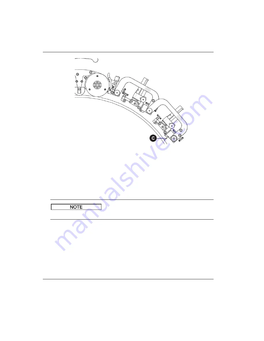
Figure 4

113  Align probes with the scan surface tangent

4.10.2

Pivoting Probe Holder Rack

The pivoting probe holder rack uses vertical probe holders (see Figure 4-114 on 
page 177).
 The SteerROVER can guide as many as 6 probes in the longitudinal and 
circumferential direction. 

A minimum OD of 305 mm (12 in.) is required for longitudinal scanning. 

NOTE

Summary of Contents for SteerROVER

Page 1: ...r s Manual This instruction manual contains essential information on how to use this Olympus product safely and effectively Before using this product thoroughly review this instruction manual Use the...

Page 2: ...e accuracy of the information contained therein and corresponds to the version of the product manufactured prior to the date appearing on the title page There could however be some differences between...

Page 3: ...lity 10 Repair and Modification 10 Safety Symbols 11 Safety Signal Words 12 Note Signal Words 13 Safety 13 Warnings 13 Equipment Disposal 18 CE European Community 18 WEEE Directive 19 China RoHS 19 Ko...

Page 4: ...ual Drive Modules with Pivoting Probe Holder Rack 50 2 5 Dual Drive Modules with Probe Holder Rack for Flange Scanning 52 2 6 Single Drive Module with Frame Bar 54 3 Operation 57 3 1 System Start Up 5...

Page 5: ...le 121 4 8 1 Mounting a Raster Arm Flat or Circumferential 121 4 8 2 Mounting a Raster Arm Longitudinal 123 4 8 3 Attaching a Cable Tray 124 4 8 4 Routing Cables through the Cable Tray 127 4 8 5 Setti...

Page 6: ...ble Management 189 4 12 2 Setting Up the Cable Management 190 4 12 3 Attaching the Cable Management Clamp 192 4 13 Backpack Optional 193 4 14 Pre Amp Bracket Optional 196 5 Maintenance 199 5 1 Safety...

Page 7: ...A 3 4 Cable Tray Parts 230 A 3 5 Cable Carrier 231 A 3 6 Heavy Duty Vertical Probe Holder Components 232 A 4 Pivoting Probe Holder Rack Components 234 A 4 1 Frame Bar 235 A 4 2 Vertical Probe Holder...

Page 8: ...10 004209 01EN Q7750159 Rev 2 May 2018 Table of Contents viii...

Page 9: ...10 004209 01EN Q7750159 Rev 2 May 2018 List of Abbreviations ix List of Abbreviations EFUP environment friendly use period GFCI ground fault circuit interrupter OD outside diameter...

Page 10: ...10 004209 01EN Q7750159 Rev 2 May 2018 List of Abbreviations x...

Page 11: ...tion labels are attached to the instrument or engraved at the locations shown in Figure i 1 on page 2 Figure i 2 on page 3 and Figure i 3 on page 3 Label details are provided in Table 1 on page 4 Symb...

Page 12: ...01EN Q7750159 Rev 2 May 2018 Labels and Symbols 2 Figure i 1 Label locations on scanner and accessories Safety and rating labels Rating label Rating label Olympus logo Safety label Olympus logo and ra...

Page 13: ...3 Figure i 2 Label and engraving locations on the SteerROVER right drive module Figure i 3 Label and engraving locations on the SteerROVER left drive module Right drive module side view Olympus addres...

Page 14: ...10 004209 01EN Q7750159 Rev 2 May 2018 Labels and Symbols 4 Table 1 SteerROVER labels ID no Part Labels Drive modules Right drive module Left drive module Module cables Module casing...

Page 15: ...10 004209 01EN Q7750159 Rev 2 May 2018 Labels and Symbols 5 Power controller Raster arm Umbilical Handheld controller Table 1 SteerROVER labels continued ID no Part Labels...

Page 16: ...The model number S N The serial number The regulatory compliance mark RCM label indicates that the product complies with all applicable standards and has been registered with the Australian Communicat...

Page 17: ...ser shall be noticed that this equipment is suitable for electromagnetic equipment for office work class A and it can be used outside home The MSIP code for the SteerROVER is the following MSIP REM OL...

Page 18: ...10 004209 01EN Q7750159 Rev 2 May 2018 Labels and Symbols 8...

Page 19: ...ials Do not use the SteerROVER for any purpose other than its intended use It must never be used to inspect or examine human or animal body parts Instruction Manual This instruction manual contains es...

Page 20: ...sed Always use equipment and accessories that meet Olympus specifications Using incompatible equipment could cause equipment malfunction and or damage or human injury Repair and Modification The Steer...

Page 21: ...least 25 cm 10 in away at all times In order to prevent human injury and or equipment damage do not disassemble modify or attempt to repair the instrument Safety Symbols The following safety symbols m...

Page 22: ...word until the indicated conditions are fully understood and met The WARNING signal word indicates a potentially hazardous situation It calls attention to a procedure practice or the like that if not...

Page 23: ...renthetical information that is useful but not imperative The TIP signal word calls attention to a type of note that helps you apply the techniques and procedures described in the manual to your speci...

Page 24: ...ck may result Do not allow metallic or foreign objects to enter the device through connectors or any other openings Otherwise a malfunction or electric shock may result Electrical Warnings Before oper...

Page 25: ...below a SteerROVER must be kept clear at all times A clearly marked NO ENTRY ZONE must be cordoned off directly below the area of scanner operation see No Entry Fall Zone on page 17 for additional de...

Page 26: ...ZARDOUS Misuse can result in FIRE or DEATH by ELECTRICAL SHOCK Inspect thoroughly before each use Do NOT use if damaged Do NOT use when wet Keep away from water Do NOT drive drag or place objects over...

Page 27: ...e area of scanner operation according to the dimensions shown below CAUTION DO NOT operate the SteerROVER scanner on an inspection surface that is electrically connected to a component that is being w...

Page 28: ...ler operation Equipment Disposal Before disposing of the SteerROVER check your local laws rules and regulations and follow them accordingly CE European Community This device complies with the requirem...

Page 29: ...his symbol indicates that the product must not be disposed of as unsorted municipal waste but should be collected separately Refer to your local Olympus distributor for return and or collection system...

Page 30: ...may cause interference The SteerROVER has been tested and found to comply with the limits for an industrial device in accordance with the specifications of the EMC directive FCC USA Compliance This d...

Page 31: ...a Warranty Information Olympus guarantees your Olympus product to be free from defects in materials and workmanship for a specific period and in accordance with conditions specified in the Olympus Sci...

Page 32: ...the requirements of any particular application Olympus reserves the right to modify any product without incurring the responsibility for modifying previously manufactured products Technical Support Ol...

Page 33: ...in for vertical surfaces 1 mm 0 040 in for horizontal surfaces on which the crawler is right side up Be free of excess rust scale ferrous debris ice and frost Have a minimum thickness of 3 mm 0 120 i...

Page 34: ...and specifications in this manual could result in SEVERE INJURY or DEATH The SteerROVER is NOT intended for Operation on surfaces that are not clean ex excess rust scale ferrous debris ice or frost Li...

Page 35: ...greater than 2 m 6 ft the SteerROVER is intended to be used by two people A person who is trained in rigging and fall protection as well as able to effectively apply the same safety principals to the...

Page 36: ...26 Figure i 5 3 mm hex driver Also included in this kit is a 0 375 in wrench which is used to remove and install probe holder buttons see Figure i 6 on page 26 Figure i 6 0 375 in wrench The included...

Page 37: ...flat screwdriver Optional Tools There are some specialized adjustments require tools that are not included with this kit see Figure i 8 on page 27 1 5 mm hex wrench 2 mm hex wrench 2 5 mm hex wrench 3...

Page 38: ...10 004209 01EN Q7750159 Rev 2 May 2018 Introduction 28...

Page 39: ...d to slam onto the walls of the opening 1 2 No Entry Fall Zone FALLING OBJECT HAZARD The area below the SteerROVER must be kept clear at all times A clearly marked NO ENTRY FALL ZONE must be cordoned...

Page 40: ...ii must be no smaller than 3 m 10 ft from the area below the area of crawler operation 1 3 Tether Requirements and Attachment FALLING OBJECT HAZARD Failure to comply with the warnings instructions and...

Page 41: ...ith a proper tether system to prevent the scanner from falling The tether system must Be capable of safely suspending the SteerROVER from above in case the scanner detaches from the inspection surface...

Page 42: ...mize dangerous swinging of the scanner should it detach from the inspection surface Carefully inspect the lifting sling for damage prior to each use Ensure the tether hook does not have sharp edges th...

Page 43: ...ration for Use 33 Figure 1 2 Lifting the tether attachment points 2 Simultaneously press the pin s release button and pull the pin from the shackle see Figure 1 3 on page 33 Figure 1 3 Press the pin s...

Page 44: ...und the tether attachment point see Figure 1 4 on page 34 left 4 Align the tether attachment point and shackle and then insert the pin while pressing the pin s release button see Figure 1 4 on page 34...

Page 45: ...correct right orientation of the shackles Figure 1 5 Proper shackle left incorrect shackle right orientation 1 3 2 Lifting Sling Low Profile Setup The shackle plate in conjunction with the tether atta...

Page 46: ...apter 1 36 Figure 1 6 Location of the shackle plate To secure the lifting sling to the SteerROVER Reverse the lifting sling and shackles so the shackles are free to lay down flat allowing for low prof...

Page 47: ...utlined in Intended Use on page 23 and Unintended Use on page 24 of this manual To prepare the inspection surface 1 Remove build up of scale and other debris ex dirt ice from the surface on which the...

Page 48: ...Components on page 93 Table 4 SteerROVER packages part numbers Part number Package description Q7500050 SteerROVER scanner and standard accessories inclusion with pivoting probe holder rack including...

Page 49: ...ries with 900 mm 3 ft raster arm heavy duty vertical probe holder and 7 5 m cables Q7500057 SteerROVER scanner and standard accessories inclusion with 900 mm 3 ft raster arm heavy duty vertical probe...

Page 50: ...ules Power controller P N Q7201262 Handheld controller P N Q7750089 Encoder cable Controller cable Lifting sling Cable management Umbilical Pivoting probe holder rack P N Q7201258 included with weld p...

Page 51: ...continued Raster arm length depends on package selected Dual conventional UT probe holder P N Q7750070 optional Laser guide optional Pre amp bracket P N Q7201260 optional Irrigation kit Backpack P N...

Page 52: ...10 004209 01EN Q7750159 Rev 2 May 2018 Chapter 1 42...

Page 53: ...ev 2 May 2018 Configurations 43 2 Configurations This chapter contains information on making the connections to configure the SteerROVER for scanning For a detailed view of the umbilical connectors se...

Page 54: ...Description ID Description ID User s instrument 1 Controller cable alt 5b Right drive module 10 Encoder cable 2 Power controller 6 Raster arm optional 11 Power cable 3 Umbilical 7 Heavy duty vertical...

Page 55: ...1 on page 44 2 Connect the umbilical to the power controller 3 Connect the handheld controller to the power controller using the controller cable The handheld controller may also be connected directly...

Page 56: ...Description ID Description ID User s instrument 1 Controller cable alt 5b Right drive module 10 Encoder cable 2 Power controller 6 Raster arm optional 11 Power cable 3 Umbilical 7 Dual conventional UT...

Page 57: ...age 46 2 Connect the umbilical to the power controller 3 Connect the handheld controller to the power controller using the controller cable The handheld controller may also be connected directly to th...

Page 58: ...ion ID Description ID User s instrument 1 Controller cable alt 5b Right drive module 10 Encoder cable 2 Power controller 6 Raster arm optional 11 Power cable 3 Umbilical 7 Dual probe holder optional 1...

Page 59: ...Connect the umbilical to the power controller 3 Connect the handheld controller to the power controller using the controller cable The handheld controller may also be connected directly to the umbili...

Page 60: ...rack optional configuration Description ID User s Instrument 1 Encoder cable 2 Power cable 3 Handheld controller 4 Controller cable main 5a Controller cable alt 5b Power controller 6 Umbilical 7 Left...

Page 61: ...e system for scanning using a probe holder rack 1 Connect the power controller to the umbilical see Figure 2 4 on page 50 2 Connect the umbilical to SteerROVER scanner 3 Connect the handheld controlle...

Page 62: ...r scanning using dual drive modules with a pivoting probe holder rack configured for flange scanning follow this procedure Description ID User s instrument 1 Encoder cable 2 Power cable 3 Handheld con...

Page 63: ...age 52 2 Connect the umbilical to the power controller 3 Connect the handheld controller to the power controller using the controller cable The handheld controller may also be connected directly to th...

Page 64: ...6 Right drive module configuration Description ID User s instrument 1 Encoder cable 2 Power cable 3 Handheld controller 4 Controller cable main 5a Controller cable alt 5b Power controller 6 Umbilical...

Page 65: ...ng Connecting the Left and Right Drive Modules on page 106 2 Mount and connect the umbilical to the right drive module see Figure 2 6 on page 54 3 Connect the power controller to the umbilical 4 Conne...

Page 66: ...10 004209 01EN Q7750159 Rev 2 May 2018 Chapter 2 56...

Page 67: ...on FALLING OBJECT HAZARD Ensure the umbilical can freely uncoil during operation and does not become snagged If the umbilical becomes snagged the SteerROVER may fall and SEVERE INJURY or DEATH could r...

Page 68: ...controller activates the system see item 2 Figure 3 1 on page 57 A warning message displays on the handheld controller when power has been activated see Figure 3 2 on page 58 Figure 3 2 Handheld contr...

Page 69: ...nd adjust accordingly When a raster arm is detected a warning appears indicating the carriage must move to the home position see Figure 3 4 on page 59 Figure 3 4 Raster homing 6 Ensure the raster arm...

Page 70: ...teerROVER installation is done at elevated heights improper use may cause the scanner to fall and SEVERE INJURY or DEATH could result To prevent equipment damage do NOT handle the SteerROVER using the...

Page 71: ...anner via the handheld controller 1 After the SteerROVER preparation is complete see Preparation for Use on page 29 raise the front swivel mounts see Swivel Mount on page 95 using the swivel mount adj...

Page 72: ...t the SteerROVER to Jog mode see Jog Mode on page 69 3 Place the installation removal mat on the inspection surface Figure 3 7 on page 62 Figure 3 7 Place installation removal mat 4 Place and hold the...

Page 73: ...four wheels of the SteerROVER are held firmly against the installation removal mat 6 While holding the SteerROVER use the Fwd Rev joystick see Figure 3 9 on page 64 to carefully drive the scanner see...

Page 74: ...10 004209 01EN Q7750159 Rev 2 May 2018 Chapter 3 64 Figure 3 9 Drive the SteerROVER Figure 3 10 Drive SteerROVER off the mat...

Page 75: ...urface 7 Remove the installation removal mat from the inspection surface Circumstance may arise when only one person is available for placement of the SteerROVER on a inspection surface With the syste...

Page 76: ...2018 Chapter 3 66 Figure 3 12 Swivel mount aligned parallel to scan surface 3 3 Handheld Controller Layout This section contains explanations about the components of the handheld controller including...

Page 77: ...handheld controller touchscreen see Figure 3 13 on page 67 is the primary operator interface for the system Buttons are indicated on the screen with a 3D border see Figure 3 14 on page 68 ID Descripti...

Page 78: ...selection Rotating the click wheel selects different buttons on the screen Press the click wheel to choose the button currently selected 3 3 3 Joysticks The joysticks are used to control the system T...

Page 79: ...80 3 4 1 Jog Mode Jog mode manually controls the system movement using the joystick Jog mode is the default selection when the system is first activated When a raster arm is connected see Raster Arm...

Page 80: ...de showing the position and speed of the SteerROVER Button Identification The following descriptions identify the buttons of the Jog Mode screen see Figure 3 18 on page 70 and Figure 3 19 on page 72 a...

Page 81: ...ight SteerROVER module is connected the position displayed under Crawler refers to the position of the auxiliary idler encoder which is located between the drive module s wheels This function only zer...

Page 82: ...screen When Raster is selected the right joystick is used to control the raster arm movement The system automatically limits movement to the mechanical end limits of the raster arm Figure 3 19 Jog mod...

Page 83: ...and REV buttons are located on the Crawler tab Press the FWD or REV button to drive the SteerROVER at the current maximum scan rate When the SteerROVER is in motion the raster joystick is still enabl...

Page 84: ...een The Two Axis Scan Setup screen is used to program the desired scan pattern the system will use Point A The current position of the SteerROVER and index axis The A position may also be set while in...

Page 85: ...ed Each point and setting A B C D corresponds to a coordinate entry button on the right side of the screen A typical scan begins at the A position and moves to the B position Scanning begins at the B...

Page 86: ...Scan Speeds Screen on page 77 Run button Initiates a check of the input values to ensure they are within the system capabilities When a scan pattern is invalid a warning will be displayed see Figure...

Page 87: ...4 3 2 Scan Speeds Screen The Scan Speeds screen see Figure 3 25 on page 77 is where you adjust speed settings for two axis scanning Scan speeds may be adjusted in the Jog Mode or User Settings screen...

Page 88: ...n area described by the B and C positions The blinking cross hair 2 indicates the current scanner position The current position of the scan 4 and index 5 axis are displayed When a right drive module i...

Page 89: ...ng a scan a graphical representation of the scanner path is displayed see Figure 3 27 on page 79 Figure 3 27 Scan path When the scanner reaches the scan area the graphic zooms to display that scan are...

Page 90: ...ition of the scanner will be changed to the current position Figure 3 29 Exit warning Press Back to return to the Two Axis Scan screen to reset the scanner and maintain original A position Press Conti...

Page 91: ...n Touch Cal button Used to initiate the Touch Calibration screen Joystick Cal button Used to enter the Joystick Calibration screen Draw button Enters the mode used to test the touchscreen accuracy and...

Page 92: ...s Title Description Valid range Default Units In 0 MM 1 Changes the measurement units used for display and user entry When set to 0 units measure in inches When set to 1 units measure in millimeters 0...

Page 93: ...in s Crawler Rapid unit s Sets the SteerROVER rapid rate in the current units second This setting can also be changed through the Jog screen 0 254 mm s 0 10 in s 254 mm s 10 in s Raster Scan unit s Se...

Page 94: ...er Flip 0 1 Sets the raster arm orientation When the raster arm is mounted with the motor housing to the left of the SteerROVER the appropriate setting is 1 When the raster arm is mounted with the mot...

Page 95: ...re version and it displays which modules were detected when the system was activated see Figure 3 32 on page 85 Figure 3 32 The Detected Modules screen System 1 The System 1 diagnostic screen displays...

Page 96: ...ct System 2 Additional general system function information is displayed on the System 2 screen see Figure 3 34 on page 86 An empty button is provided to allow testing of the click wheel Figure 3 34 Th...

Page 97: ...y assist the user Figure 3 35 The System 3 Diagnostics screen LeftDrv RightDrv or Raster The LeftDrv RightDrv and Raster diagnostic screens provide information regarding the status of each motorized m...

Page 98: ...ol system is responding to forces on the module s motor Temperature Internal temperature reading of the module in degrees Celsius AuxEncPos Displays the position of the auxiliary encoder in counts whe...

Page 99: ...markers be touched with a small object to enhance the touch position accuracy during calibration The new calibration is stored immediately when the fourth marker is pressed The calibration utility ex...

Page 100: ...rate to 0 The new calibration is stored when the Exit button is pressed It may be necessary to validate that the calibration is centered by testing each joystick in both directions If one direction re...

Page 101: ...eration 91 Figure 3 40 The Joystick Calibration screen 3 4 4 5 Draw Utility The draw utility may be used to test the function of the touchscreen see Figure 3 41 on page 91 Exit the utility by pressing...

Page 102: ...ve equipment when removing the SteerROVER from a high temperature surface When the system approaches its maximum operating temperature the high internal temperature screen will display see Figure 3 42...

Page 103: ...r settings and scan information are edited using the handheld controller The handheld controller is connected to the power controller or the umbilical with the controller cable see Figure 1 8 on page...

Page 104: ...uld occur 4 2 Right Drive Module The right drive module includes the encoder umbilical connections and accessory mounting point When connected with the left drive module the SteerROVER scanner is able...

Page 105: ...e swivel mount is used to connect scanning accessories such as a raster arm module or probe frame system Rotate the two black wing knobs to loosen the dovetail jaws see Figure 4 3 on page 95 Slide the...

Page 106: ...Figure 4 4 Swivel mount angle Alternatively accessories can also be mounted straight to the swivel mount Rotate the black wing knobs aligning the dovetail jaws with the mount s grooves see Figure 4 5...

Page 107: ...nate mounting procedure is possible see Swivel Mount on page 95 for additional details The etched line near the base of the swivel mount can be used to align the front swivel mount to a horizontal pos...

Page 108: ...tched line The front mount must be horizontal when using the pivoting probe holder rack to scan longitudinally on piping 4 2 2 Umbilical To mount the umbilical to the SteerROVER 1 Connect the umbilica...

Page 109: ...t to umbilical 2 Align the umbilical to the umbilical mount of the drive module see Figure 4 10 on page 99 Figure 4 10 Align with drive module mount 3 Fasten the umbilical to the SteerROVER scanner s...

Page 110: ...r to position the umbilical mount at the desired angle see Figure 4 12 on page 101 The SteerROVER scanner s umbilical mount can pivot to allow low profile scanning Always ensure the right drive module...

Page 111: ...ure to set the umbilical height as described below may cause the SteerROVER to fall and SEVERE INJURY or DEATH could result 5 If you are scanning at heights greater than 2 m 6 ft set the umbilical so...

Page 112: ...ight drive module includes an independent encoder wheel see Figure 4 15 on page 103 This encoder wheel provides accurate encoding even in the event of drive wheel slip The spring loaded encoder wheel...

Page 113: ...coder wheel 4 2 4 Handle The handle can be removed to achieve low profile scanning To remove the handle 1 Lift the handle lock latch see Figure 4 16 on page 103 Figure 4 16 Lift the handle lock latch...

Page 114: ...from the SteerROVER drive module see Figure 4 18 on page 104 To reinstall the handle perform the preceding steps in reverse Figure 4 18 Lift the handle to remove it 4 2 5 Dovetail Accessory Mount Aff...

Page 115: ...oth modules allows the SteerROVER scanner to steer on an inspection surface MAGNETIC MATERIAL The wheels of the SteerROVER produce an extremely strong magnetic field that may cause failure or permanen...

Page 116: ...ear of pinch points when connecting disconnecting the left and right drive modules This operation is best performed by two people To disconnect the left and right drive modules 1 Locate the release pi...

Page 117: ...ponents 107 Figure 4 21 Press release pin Figure 4 22 Press pin and rotate modules 2 Continue rotating the two modules until they are 90 perpendicular see Figure 4 23 on page 108 and then gently pull...

Page 118: ...10 004209 01EN Q7750159 Rev 2 May 2018 Chapter 4 108 Figure 4 23 Rotate modules to 90 Figure 4 24 Pull modules apart 3 Label the left drive module with a magnetic warning that is clearly visible...

Page 119: ...to protect the connection pivots from dirt dust mud etc see Figure 4 25 on page 109 When the drive modules are separated it is imperative that the connection pivots remain free of dirt sand mud etc If...

Page 120: ...to be connected to the umbilical To connect the umbilical to the left drive module Connect the cord of the left drive module to the 8 pin connector of the umbilical indicated in Figure 4 26 on page 11...

Page 121: ...black wing knobs to clamp the frame system raster arm in place see Figure 4 27 on page 111 Figure 4 27 Frame bar installation The front mount pivots freely and cannot be locked in a fixed position se...

Page 122: ...nd attached in the same way as the handle on the right drive module See Handle on page 103 for instructions 4 3 6 Dovetail Accessory Mount The dovetail accessory mount on the left drive module works i...

Page 123: ...ne before power can be activated The control cable connects to the CTRL socket 1 The encoder cable connects to the ENC socket 2 The status LCD screen 6 displays the power controller system s status Co...

Page 124: ...generators or DC AC inverters may introduce significant levels of noise to the system This may degrade overall system performance or reduce the system life expectancy Use of generators or DC AC invert...

Page 125: ...all power network distribution as well as encoder signal transmission Circuitry is incorporated into the umbilical to protect or isolate all signals The umbilical provides separation between the power...

Page 126: ...mary X 4 in Figure 4 31 on page 116 or secondary Y 2 encoder axis The third unlabeled receptacle 3 contains no encoder wiring Figure 4 31 Umbilical connectors scanner side ID Description 1 Not used 2...

Page 127: ...ency off button to the entire system When pressed all power to the SteerROVER scanner system is disengaged To restore system power it is necessary to press the green power button located on the power...

Page 128: ...xiliary encoder failure with the right drive module the right and left drive modules connectors may be swapped see Encoder Failure on page 208 for instructions This transmits encoder signals from the...

Page 129: ...ty hazard and could also put other system components at risk The controller cable connects the handheld controller to the umbilical 36 VDC and network signals are used in the cable see Figure 4 33 on...

Page 130: ...trument This cable allows transmission of necessary two axis position signals from the SteerROVER system to the instrument see Figure 4 34 on page 120 The encoder cable also provides 5 VDC from your i...

Page 131: ...array probes as well as scanning devices such as the Olympus HydroFORM The handheld controller is used to setup all the parameters of the scan see Two Axis Scan Mode on page 73 for additional details...

Page 132: ...raster arm s mounting rail onto the dovetail jaws of one of the modules see Figure 4 36 on page 122 Figure 4 36 Slide onto one swivel mount 2 Release the swivel mount levers and pivot the swivel moun...

Page 133: ...4 8 2 Mounting a Raster Arm Longitudinal To mount a raster arm for longitudinal scanning 1 Using the 3 mm hex driver attach the probe holder mount optional P N Q8301377 to the mounting rail of the ra...

Page 134: ...ight drive module s swivel mount see Figure 4 39 on page 124 Figure 4 39 Mount raster arm to the right drive module s swivel mount 3 Tighten the two black wing knobs 4 8 3 Attaching a Cable Tray To at...

Page 135: ...10 004209 01EN Q7750159 Rev 2 May 2018 System Components 125 Figure 4 40 Attaching the cable tray 2 Press the cable tray bracket into the rear of the carriage bracket see Figure 4 41 on page 126...

Page 136: ...1EN Q7750159 Rev 2 May 2018 Chapter 4 126 Figure 4 41 Press bracket to carriage 3 Slide the cable tray bracket until it locks in place see Figure 4 42 on page 126 Figure 4 42 Slide bracket attaching t...

Page 137: ...trudes 4 8 4 Routing Cables through the Cable Tray To route cables through the cable tray 1 Using a small 3 mm flat screw driver unclip the flaps of the cable tray see Figure 4 43 on page 127 Figure 4...

Page 138: ...nvenient by removing several flaps in a row at the same time 4 8 5 Setting Up the Raster Arm Cable The raster arm cable connects the raster arm module to the umbilical The cable provides the 36 VDC an...

Page 139: ...encoder signal via the umbilical and encoder cable to the acquisition instrument The raster arm cable may be connected to any of the other 8 pin receptacles on the umbilical for troubleshooting or non...

Page 140: ...page 130 located on the raster arm encoder housing Figure 4 46 Raster arm cable routing 2 Pinch the cable into the first cable bracket on the side of the raster arm encoder housing 3 Route the cable t...

Page 141: ...e sure that the cable clears the scanner wheels Do not tighten or loosen the clip screws These clip screws have been specially torqued by the manufacturer to allow for friction movement The clips have...

Page 142: ...Duty Vertical Probe Holder on page 150 for instructions on mounting the probe holders 4 9 Probe Holders This section provides information on the components of the probe holders and how to set up and...

Page 143: ...mponents 133 Figure 4 49 Vertical probe holder Table 6 Vertical probe holder components Item Description A Latch B Probe holder adjustment knob C Vertical adjustment knob D Pivot buttons E Probe holde...

Page 144: ...d to a frame bar and it also enables horizontal positioning on a frame bar see Figure 4 50 on page 134 Figure 4 50 Adjust on frame bar The vertical adjustment knob is used to adjust the height of the...

Page 145: ...ical adjustment Position the pivot buttons where necessary When a narrow scanning footprint is required use the pivot button holes that are closest to the yoke see Figure 4 52 on page 135 Figure 4 52...

Page 146: ...er yoke can accommodate many different probe and wedge sizes of varying widths It is best to center the wedge with the yoke s pivot axis This can reduce wedge rocking when scanning Position the inner...

Page 147: ...rm adjustment knob see Figure 4 55 on page 137 Figure 4 55 Tighten arm knob 4 9 1 2 Probe Holder Vertical Adjustment To adjust the probe holder vertically 1 Ensure the probe holder is in the latched u...

Page 148: ...is approximately 6 mm 0 25 in above inspection surface see Figure 4 57 on page 138 and then tighten the vertical adjustment knob Figure 4 57 Lower toward scan surface 3 Lift the yoke slightly and pres...

Page 149: ...ev 2 May 2018 System Components 139 Figure 4 58 Press latch button Figure 4 59 Lower toward scan surface If less spring force is desired see step 2 and place the wedge approximately 20 mm 0 75 in abov...

Page 150: ...e probe holder is in the latched upper position see Figure 4 56 on page 138 2 Using the supplied 3 mm hex driver loosen the transverse adjustment screw and rotate the yoke about the vertical shaft ach...

Page 151: ...he transverse adjustment to neutral 90 the probe holder must be in the latched upper position see Figure 4 56 on page 138 Rotate the yoke until the stop post contacts the base of the probe holder and...

Page 152: ...ongitudinal scanning 1 Ensure the probe holder is in the latched upper position see Figure 4 56 on page 138 2 Using the supplied 3 mm hex driver loosen the longitudinal adjustment screw see Figure 4 6...

Page 153: ...ure 4 64 Rotate to position 4 Tighten the longitudinal adjustment screw see Figure 4 64 on page 143 5 To return the longitudinal adjustment to neutral 90 line up the longitudinal adjustment indicator...

Page 154: ...s required 1 Ensure the probe holder is in the latched upper position see Figure 4 56 on page 138 2 Using the supplied 3 mm hex driver unscrew the yoke pivot screw and remove the yoke see Figure 4 66...

Page 155: ...67 Remove probe holder arms 4 Flip the yoke 180 and reverse the probe holder arms see Figure 4 68 on page 145 Figure 4 68 Flip yoke and reverse arms 5 Place the pivot buttons on the inside of the pro...

Page 156: ...buttons 6 Mount the yoke to the opposite side of the base using the supplied 3 mm hex driver see Figure 4 70 on page 146 Figure 4 70 Screw yoke to opposite side Keep the yoke level with the base to e...

Page 157: ...using a 1 5 mm hex wrench until it has cleared all obstructions Do not remove stop post see Figure 4 71 on page 147 Figure 4 71 Lower 90 stop post 8 Raise the stop post on the opposite side until the...

Page 158: ...Holder Optional The pivoting HydroFORM probe holder is designed to function with the Olympus HydroFORM scanner not provided To use pivoting HydroFORM probe holder 1 Rotate the probe holder adjustment...

Page 159: ...der arm adjustment knob can be rotated see Figure 4 75 on page 149 This allows placement of the HydroFORM by positioning the probe holder arm accordingly Figure 4 75 Arm adjustment 2 Lift the probe ho...

Page 160: ...50159 Rev 2 May 2018 Chapter 4 150 Figure 4 76 Lift and pull latch 4 9 3 Heavy Duty Vertical Probe Holder Figure 4 77 on page 151 and Table 7 on page 151 identify the components of the heavy duty vert...

Page 161: ...igure 4 77 Heavy duty vertical probe holder Table 7 Heavy duty vertical probe holder ID Description A Latch B Probe holder arm adjustment knob C Yoke D Probe holder arms E Pivot buttons F Arm clamp sc...

Page 162: ...the carrier see Figure 4 78 on page 152 Figure 4 78 Mount probe holder to carrier The vertical adjustment knob is used to adjust the height of the heavy duty vertical probe holder see Figure 4 79 on...

Page 163: ...outer arm 3 Loosen the arm clamp screw see Figure 4 81 on page 153 4 Place the wedge on the pivot button of the inner probe holder arm see Figure 4 81 on page 153 Figure 4 81 Adjust inner arm 5 Align...

Page 164: ...y 2018 Chapter 4 154 Figure 4 82 Remove outer arm 6 Tighten both the probe holder adjustment knob and the arm clamp screw while ensuring the wedge remains centered with the yoke see Figure 4 83 on pag...

Page 165: ...probe holder vertically 1 Gently lift the heavy duty probe holder and simultaneously pull the latch to unlock the probe holder see Figure 4 84 on page 155 Figure 4 84 Press up and pull latch 2 Slowly...

Page 166: ...ersion To convert the probe holder from left to right 1 Using the supplied 3 mm driver unscrew the yoke see Figure 4 86 on page 156 Figure 4 86 Remove yoke 2 Position the yoke and arms to the opposite...

Page 167: ...e probe holder arm adjustment knob allowing removal of the probe holder arms see Figure 4 88 on page 157 Figure 4 88 Remove probe holder arms 4 Reverse the position of the removed arms so they are at...

Page 168: ...e holder arms see Figure 4 90 on page 158 Figure 4 90 Position pivot buttons 6 Place the probe holder arms on the yoke and tighten the arm clamp screw and probe holder adjustment knob see Figure 4 91...

Page 169: ...ke using the supplied 3 mm hex driver 2 Orient the yoke to the front of the probe holder and screw the yoke into the threaded hole provided 4 9 4 Dual Conventional UT Probe Holder Optional Follow thes...

Page 170: ...018 Chapter 4 160 Figure 4 92 Pinch the cable clip to remove It is necessary to remove the mounting bracket of the dual conventional UT probe holder if attached 2 Rotate the probe holder adjustment kn...

Page 171: ...nts 161 Figure 4 93 Loosen knob 3 Remove the mounting bracket see Figure 4 94 on page 161 Figure 4 94 Remove bracket 4 Insert the dovetail jaw of the dual conventional UT probe holder see Figure 4 95...

Page 172: ...4 95 Insert the dovetail jaw in raster arm pivot nose 5 Tighten the probe holder adjustment knob see Figure 4 96 on page 162 Figure 4 96 Tighten knob 6 Release the two levers on the swivel mount to a...

Page 173: ...Rev 2 May 2018 System Components 163 Figure 4 97 Pivot raster arm 7 Align the raster arm so that it is parallel with the tangent of the scan surface see Figure 4 98 on page 163 Figure 4 98 Align para...

Page 174: ...the position of the raster arm 9 Release the raster arm pivot nose latch see Figure 4 99 on page 164 Figure 4 99 Adjust raster arm pivot nose 10 Lower the probe holder to a minimum of 20 mm 0 75 in a...

Page 175: ...4 100 Latch the raster arm pivot nose 11 Gently lift the probe holder see Figure 4 101 on page 166 1 12 Pull the probe holder latch see Figure 4 101 on page 166 2 13 Lower the probe holder gently to t...

Page 176: ...0159 Rev 2 May 2018 Chapter 4 166 Figure 4 101 Pull probe latch to release dual conventional UT probe holder 4 9 5 Dual Probe Holder Configuration To mount two probe holders to the raster arm follow t...

Page 177: ...nt equipment damage do not mount more than two probe holders to the front of the raster arm To install dual probe holders 1 Remove the cable tray see Attaching a Cable Tray on page 124 2 Using the sup...

Page 178: ...v 2 May 2018 Chapter 4 168 Figure 4 103 Remove pivot nose 3 Release the side lever of the raster arm pivot nose male and angle the raster arm pivot nose downward see Figure 4 104 on page 168 Figure 4...

Page 179: ...018 System Components 169 4 Mount the male pivot nose sold separately to the raster arm see Figure 4 105 on page 169 Figure 4 105 Install the male pivot nose 5 Mount a frame bar to the raster arm pivo...

Page 180: ...Rev 2 May 2018 Chapter 4 170 Figure 4 106 Mount frame bar 6 Follow the steps in Probe Holder Setup on page 134 to mount and set up the vertical probe holders see Figure 4 107 on page 170 Figure 4 107...

Page 181: ...or Circumferential on page 171 contain images of a probe holder rack with straight nonpivoting frame bars the same principles apply to the pivoting probe holder rack 4 10 1 Probe Holder Rack Flat or...

Page 182: ...ch the wedges to the probe holders that will be used see Probe Holder Setup on page 134 for additional details 2 Affix the probe holders with attached wedges to the probe holder rack Place the seconda...

Page 183: ...see Swivel Mount on page 110 for additional details When mounting the probe holder rack ensure the attachment knobs are at the front not the scanner side see Figure 4 110 on page 174 To avoid mechanic...

Page 184: ...ce 4 Release the two swivel mount levers see Figure 4 110 on page 174 to position the swivel mount parallel to the scan surface see Figure 4 111 on page 174 When alignment with scan surface is achieve...

Page 185: ...74 Ensure that gap B see Figure 4 112 on page 175 is no smaller than gap A see Figure 4 111 on page 174 Figure 4 112 Set front rotational adjustment knob 6 Loosen the front rotational adjustment knob...

Page 186: ...e tangent 4 10 2 Pivoting Probe Holder Rack The pivoting probe holder rack uses vertical probe holders see Figure 4 114 on page 177 The SteerROVER can guide as many as 6 probes in the longitudinal and...

Page 187: ...and right hand swivel mounts may cause the SteerROVER to fall and SEVERE INJURY or DEATH could result To mount a pivoting probe holder rack 1 Attach the wedges that are to be used with the probe hold...

Page 188: ...er 4 178 Figure 4 115 Connect rack to right drive module Phased array wedges are designed to be pulled along a scan surface 3 Mount the pivoting probe holder rack to the SteerROVER scanner see Swivel...

Page 189: ...in the longitudinal direction only Only very slight corrective steering is permitted Excessive steering may cause the SteerROVER to fall and SEVERE INJURY or DEATH could result To set up the pivoting...

Page 190: ...Rev 2 May 2018 Chapter 4 180 Figure 4 116 Loosen the pivot wing knobs 2 Lower the left side of the rack system to align with the tangent of the scan surface and then tighten the pivot wing knobs see F...

Page 191: ...r the vertical probe holders see Probe Holder Vertical Adjustment on page 137 4 Ensure the probe holder arms are parallel to the scan surface see Figure 4 118 on page 181 and Probe Holder Longitudinal...

Page 192: ...vot mount can be used with the configuration in this section see Laser Guide Pivot Mount on page 185 The pivoting probe holder rack may be configured to allow scanning of flanges and the like The foll...

Page 193: ...and mount to SteerROVER 2 Loosen the pivot wing knob and raise the frame bar to an angle greater than the surface to be scanned see Figure 4 120 on page 184 Tighten the pivot wing knob and place the...

Page 194: ...er 4 184 Figure 4 120 Lift frame bar to avoid interference 3 Release the front swivel mount adjustment levers to align the swivel mount parallel to the scan surface see Figure 4 121 on page 184 Figure...

Page 195: ...er Guide Optional on page 186 To install the pivot mount see these following instructions To install the laser guide pivot mount 1 Remove the dovetail bar pivot 1 from one of the sets of probe holder...

Page 196: ...Powered Laser Guide Optional on page 186 for additional details 4 11 Battery Powered Laser Guide Optional LASER RADIATION To prevent human injury do not view directly with optical instruments Class 1...

Page 197: ...Components 187 Figure 4 124 Laser guide To setup and install the laser guide 1 Loosen the laser guide knob 2 Mount the laser guide on the frame bar and then tighten the laser guide knob see Figure 4 1...

Page 198: ...4 126 on page 188 Figure 4 126 Aim guide 4 Loosen the laser guide knob to adjust the side to side position as required 5 Retighten the laser guide knob The included perpendicular mount allows for alt...

Page 199: ...lengths and provides a means of bundling and protecting cables and hoses that connect to the SteerROVER 4 12 1 Mounting Cable Management To mount the cable management 1 Align the cable management cla...

Page 200: ...the Cable Management To set up the cable management 1 Open the cable management tube and beginning at the clamp end start placing the cabling in the tube see Figure 4 130 on page 190 Figure 4 130 Inse...

Page 201: ...able is placed in the entire length of tube bring the zipper from the opposite end to meet at any point in the middle see Figure 4 132 on page 191 Figure 4 132 Zip opposite end When necessary the two...

Page 202: ...clamp To attach the cable management clamp 1 Loosen the clamp screw using the supplied 3 mm hex driver 2 Slide the clamp around the tube and then slide the tube around the outside of the cable managem...

Page 203: ...hten clamp screw 4 13 Backpack Optional The SteerROVER backpack is intended to mount objects for example pre amps splitters etc that meet the following requirements Have a maximum weight of 1 36 kg 3...

Page 204: ...use the backpack 1 Allow the SteerROVER scanner to pivot exposing the inside of the left drive module and then slide the dovetail nuts of the backpack into the accessory dovetail groove see Figure 4...

Page 205: ...Q7750159 Rev 2 May 2018 System Components 195 Figure 4 138 Tighten screws 3 Pull the Velcro straps tight around the item on the backpack see Figure 4 139 on page 195 Figure 4 139 Velcro straps to hold...

Page 206: ...not cut pre amp bracket s straps The pre amp bracket P N Q8300570 mounts to any dovetail groove to hold a pre amp Compatible with most standard pre amps the adjustable screw mounting channel on the b...

Page 207: ...System Components 197 Figure 4 141 Pre amp in the bracket and Velcro to hold it in place 3 Mount the bracket on a frame bar and tighten the knob see Figure 4 142 on page 197 Figure 4 142 Knob to secur...

Page 208: ...10 004209 01EN Q7750159 Rev 2 May 2018 Chapter 4 198...

Page 209: ...when the E stop push button is latched in the off position MAGNETIC MATERIAL The wheels of the SteerROVER produce an extremely strong magnetic field which may cause failure or permanent damage to item...

Page 210: ...rs are free of water and moisture All components with wiring cables or electrical connections are splashproof but not submersible Never use strong solvents or abrasive materials to clean your scanner...

Page 211: ...Inspect the umbilical cable the controller cable and the power controller cable for damage Have any damaged cable repaired by a qualified person or replace the cable assembly as necessary Inspect all...

Page 212: ...10 004209 01EN Q7750159 Rev 2 May 2018 Chapter 5 202...

Page 213: ...o messages are possible in the event of a start up issue Joystick Off Center or Checking Network 6 1 1 Joystick Off Center Upon system start up the joystick positions are detected When a joystick is d...

Page 214: ...to be performed see Joystick Calibration Screen on page 89 6 1 2 Checking Network Figure 6 2 The Checking Network message During start up the system initializes the communications to all the devices...

Page 215: ...d to correct system issues Enter the maintenance mode by pressing the handheld controller click wheel while system power is activated Continue pressing the handheld controller click wheel until the St...

Page 216: ...lty Normal network speeds will be 2 for all devices When a device is not operating at the correct speed the internal software attempts to correct the device speed When a device is not operating at the...

Page 217: ...e Power screen Reset Parameters 6 2 3 System Parameters System parameters are factory set to control a variety of functions These parameters cannot be modified However special circumstances may occur...

Page 218: ...s used to track the position steering may cause wheel slippage which will affect encoder accuracy To output the motor encoder s signal plug the left drive module s connector into the umbilical s X ENC...

Page 219: ...ilical cable not properly connected Check umbilical cable connections at both ends Ensure connectors are dry and clean and connector pins are not bent SteerROVER system not started Start the SteerROVE...

Page 220: ...his table Try the solutions for problem one If the scanner is still unresponsive see Retrieval of a Stranded Scanner on page 210 SteerROVER does not steer properly A drive module is dead Contact Olymp...

Page 221: ...the scanner that is a mechanism or person must be continuously taking up slack in the tether To retrieve the scanner manually 1 Press the E stop push button to turn the SteerROVER power off Under nor...

Page 222: ...10 004209 01EN Q7750159 Rev 2 May 2018 Chapter 6 212...

Page 223: ...d Repair 213 7 Service and Repair For information about authorized service and repairs see Maintenance on page 199 For any other issues with your SteerROVER scanner first consult Troubleshooting on pa...

Page 224: ...10 004209 01EN Q7750159 Rev 2 May 2018 Chapter 7 214...

Page 225: ...neral Specifications LIFTING HAZARD The SteerROVER scanner can be heavy Single person lifting could cause injury To prevent serious human injury two person lifting is recommended Table 11 Scanner gene...

Page 226: ...ting temperature 20 C to 50 C 4 F to 122 F Maximum relative humidity 90 noncondensing Pollution degree 2 Altitude Up to 2000 m 6561 ft a Dual module configuration excluding case attachments umbilical...

Page 227: ...v 2 May 2018 Specifications 217 Figure 8 2 Scanner dimensions dual modules width and height Figure 8 3 Scanner dimensions single module width and height 28 2 cm 11 2 in 8 1 cm 3 2 in 12 5 cm 4 9 in 8...

Page 228: ...dler encoder 13 78 counts mm 349 9 counts in Left drive module motor encoder 872 5 counts mm 22162 8 counts in Raster arm module 240 2 counts mm 6100 9 counts in Environmental sealing Dust tight water...

Page 229: ...ss accompanied by the use of an uninterruptible power controller Proper grounding of the power controller is important for safe operation When a generator is used to supply power to the system not rec...

Page 230: ...ature 5 VDC RS422 compatible Power Power must be supplied to the interface 5 VDC 10 power limited to 15 W 8 7 Operating Environment The SteerROVER is designed for operation in ambient temperatures bet...

Page 231: ...Rev 2 May 2018 Spare Parts 221 Appendix Spare Parts To order accessories or replacement parts for your SteerROVER system contact Olympus These drawings are for ordering parts and not necessarily a li...

Page 232: ...SteerROVER Base Scanner Figure A 1 SteerROVER base scanner Table 14 SteerROVER base scanner spare parts ID Part number Description 1 Q8301351 Handle 2 N A Left drive module 3 N A Right drive module 4...

Page 233: ...igure A 2 Standard accessory kit components Table 15 Standard accessory kit spare parts ID Part number Description 1 Q7750088 Power controller compatible with North American or European 2 U8800512 Pow...

Page 234: ...at driver 10 Q8301352 Lifting sling 11 Q7750089 Handheld controller 12 Q8300558 Installation removal mat 13 Q8301353 Irrigation kit 2 4 probe 5 m tube Q8301354 Irrigation kit 2 4 probe 7 5 m tube Q830...

Page 235: ...25 A 2 1 Cable Management Figure A 3 Cable management parts Table 16 Cable management part numbers ID Part number Description 1 Cable sleeving see Cable Management Sleeving on page 226 2 Q8300554 Cabl...

Page 236: ...2 2 Cable Management Sleeving Figure A 4 Cable management sleeving sizes Table 17 Cable management sleeving part numbers Length Part number 4 5 m 14 8 ft Q8301380 7 m 22 9 ft Q7750093 9 5 m 31 ft Q83...

Page 237: ...ster arm Table 18 Raster arm module spare parts ID Part number Description 1 Q8300561 Pivot nose female 2 Q8300562 Cable management clip 3 Q8300563 Screw M3 0 5 4 mm 4 Mounting rail see Mounting Rail...

Page 238: ...r Description Q7500046 SteerROVER 600 mm raster arm kit Q7500047 SteerROVER 900 mm raster arm kit Q7500048 SteerROVER 1160 mm raster arm kit Q7500049 SteerROVER 300 mm raster arm kit Table 20 Mounting...

Page 239: ...the raster arm A 3 3 Cable Tray Figure A 8 Raster arm cable tray lengths Table 21 Base for raster arm part numbers Length Part number 600 mm 24 in Q8301396 900 mm 35 in Q8301397 1160 mm 46 in Q8301398...

Page 240: ...parts 1160 mm 46 in Q8301368 Table 23 Cable tray component part numbers ID Part number Description 1 Cable carrier see Cable Carrier on page 231 2 Q8301373 BHCS M5 0 8 8 mm SST 3 Q9000038 Carriage bra...

Page 241: ...igure A 10 Cable carriers 5 Q8301375 Magnetic base 6 Q8301376 Magnetic end Table 24 Cable carrier part numbers Length Part number 600 mm 24 in Q8301370 900 mm 35 in Q8301369 1160 mm 46 in Q8301370 Tab...

Page 242: ...3 6 Heavy Duty Vertical Probe Holder Components Figure A 11 Heavy duty vertical probe holder The part number of the wide yoke version of the heavy duty vertical probe holder assembly is Q7750123 and...

Page 243: ...number Description 1 Q8300592 Arm clamp screw BHCS M5 0 8 20 mm SST 2 Q8300593 Heavy duty probe holder subassembly 3 Q8300594 Probe holder arm adjustment knob 4 Q8300596 Standard yoke style S 8 28 cm...

Page 244: ...lder Rack Components Figure A 12 Pivoting probe holder rack spare parts Table 26 Pivoting probe holder rack spare parts and part numbers ID Part number Description 1 Q8300573 Vertical probe holder sid...

Page 245: ...ck right 9 Q8300567 Vertical probe holder side arm right 10 Q8301363 Male pivot to mount a probe holder bar with two 2 probes only IMPORTANT NOTE This pivot is not strong enough to support the weight...

Page 246: ...018 Appendix 236 A 4 2 Vertical Probe Holder Components for Weld Inspection Figure A 14 Vertical probe holder 45 cm 17 72 in U8830732 55 cm 21 65 in U8775161 Table 27 Frame bar spare parts and part nu...

Page 247: ...OVER weld packages see Table 4 on page 38 Table 28 Vertical probe holder spare parts and part numbers ID Part number Description 1 Q8300576 Vertical probe holder subassembly 2 Q7750010 Knurled knob M4...

Page 248: ...Figure A 15 Pivoting HydroFORM probe holder P N U8775328 Table 29 HydroFORM probe holder spare parts and part numbers ID Part number Description 1 U8775198 Pivot button style for Olympus PA wedge 2 Q8...

Page 249: ...nents Figure A 16 Dual conventional UT probe holder P N Q7750070 This probe holder P N Q7750070 is compatible with Olympus D790 probes Table 30 Dual conventional UT probe holder spare part numbers ID...

Page 250: ...y 2018 Appendix 240 A 5 3 Pre Amp Bracket Figure A 17 Pre amp bracket P N Q7201260 3 Q8300599 Screw SHSS M8 1 25 12 mm dog point SST Table 30 Dual conventional UT probe holder spare part numbers conti...

Page 251: ...Q7750159 Rev 2 May 2018 Spare Parts 241 A 5 4 Backpack Components Figure A 18 Backpack spare parts Table 31 Backpack part numbers ID Part number Description 1 Q7201261 Backpack with Velcro 2 Q8301383...

Page 252: ...Figure A 19 Laser guide spare parts or complete kit PN Q7750081 Table 32 Battery powered laser guide part numbers ID Part number Description 1 Q8301387 Perpendicular dovetail mount 2 Q8301388 Line las...

Page 253: ...rts 243 A 6 Cases A 6 1 Scanner and Accessory Cases Figure A 20 SteerROVER case options Table 33 Carrying case part numbers ID Part number Description 1 Q8301384 SteerROVER scanner case 2 Q8301385 Sca...

Page 254: ...9 Rev 2 May 2018 Appendix 244 A 6 2 Raster Arm Cases Figure A 21 Raster arm case options Table 34 Raster arm case part numbers ID Part number Description 1 Q8301371 900 mm raster arm case 2 Q8301372 6...

Page 255: ...left incorrect shackle right orientation 35 Figure 1 6 Location of the shackle plate 36 Figure 1 7 Reversing the shackle orientation for low profile scanning 37 Figure 1 8 Scanner components 40 Figure...

Page 256: ...Figure 3 24 Run button error 76 Figure 3 25 Scan speeds 77 Figure 3 26 The Two Axis Scan screen 78 Figure 3 27 Scan path 79 Figure 3 28 Scan path close up 79 Figure 3 29 Exit warning 80 Figure 3 30 Th...

Page 257: ...ing the left drive module to the umbilical 110 Figure 4 27 Frame bar installation 111 Figure 4 28 Swivel mount angle 111 Figure 4 29 Power controller 113 Figure 4 30 Umbilical cable 115 Figure 4 31 Um...

Page 258: ...ip yoke and reverse arms 145 Figure 4 69 Attach arms and move buttons 146 Figure 4 70 Screw yoke to opposite side 146 Figure 4 71 Lower 90 stop post 147 Figure 4 72 Raise opposite 90 stop post 147 Fig...

Page 259: ...mount with scan surface 174 Figure 4 111 Set rear rotational adjustment knob 174 Figure 4 112 Set front rotational adjustment knob 175 Figure 4 113 Align probes with the scan surface tangent 176 Figu...

Page 260: ...ual modules width and height 217 Figure 8 3 Scanner dimensions single module width and height 217 Figure 8 4 Pinout configuration 220 Figure A 1 SteerROVER base scanner 222 Figure A 2 Standard accesso...

Page 261: ...d accessory kit spare parts 223 Table 16 Cable management part numbers 225 Table 17 Cable management sleeving part numbers 226 Table 18 Raster arm module spare parts 227 Table 19 Raster arm complete k...

Page 262: ...Q7750159 Rev 2 May 2018 List of Tables 252 Table 31 Backpack part numbers 241 Table 32 Battery powered laser guide part numbers 242 Table 33 Carrying case part numbers 243 Table 34 Raster arm case pa...

Page 263: ...20 FCC USA 20 ICES 001 Canada 21 RCM Australia 6 component identification 38 components right drive module 94 configurations flange scanning 52 53 frame bar 55 pivoting probe holder rack 51 52 probe h...

Page 264: ...ing sling setup 32 loss of adherence 210 loss of magnetic attraction drive module wheels 37 low profile scanning setup 35 M magnetic attraction loss 37 magnetic field warning wheels 11 105 109 mainten...

Page 265: ...dual conventional UT probe holder 239 heavy duty probe holder vertical 232 kit 223 pivoting HydroFORM probe holder 238 raster arm 227 vertical probe holder optional 236 weld packages 38 specifications...

Page 266: ...warning symbols general 11 laser 12 shock hazard 11 table explanations 15 warnings electrical cord misuse 16 power source reliability 14 219 proper grounding 14 219 servicing shock hazard 10 14 explos...

Reviews: