background image

2HA/2HB

1-3-44

U343

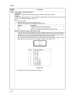
Switching between duplex/simplex copy mode
Description

Switches the Initial setting between duplex and simplex copy.

Purpose

To be set, according to frequency of use, to the more frequently used mode.

Method

Press the start key.

Setting

1. Select "on"or "oFF"using the zoom +/- keys.

Initial setting: Simplex copy 

2. Press the start key. The setting is set. The indication for selecting a maintenance item No. appears.

Completion

Press the stop/clear key. The indication for selecting a maintenance item No. appears.

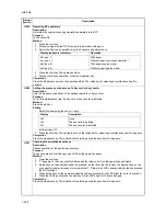
U344

Setting preheat/energy saver mode
Description

Changes the control for preheat/energy saver mode.

Purpose

To be set according to user request.

Method

Press the start key.

Setting

1. Change the setting using the zoom +/- keys.

Initial setting: ENERGY STAR 
If GEEA is set, the Auto off mode setting is fixed to ON and cannot be changed. The maximum time for 
entering the low power mode and the off mode becomes 120 minutes.

2. Press the start key. The setting is set. The indication for selecting a maintenance item No. appears.

Completion

Press the stop/clear key. The indication for selecting a maintenance item No. appears.

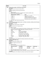
U345

Setting the value for maintenance due indication
Description

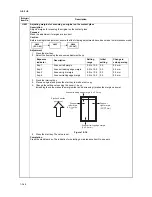
Sets when to display a message notifying that the time for maintenance is about to be reached, by setting the 
number of copies that can be made before the current maintenance cycle ends.
When the difference between the number of copies of the maintenance cycle and that of the maintenance 
count reaches the set value, the message is displayed.
This maintenance mode is effective for only Japanese specification.

Maintenance

item No.

Description

Display

Description

on

Duplex copy

oFF

Simplex copy

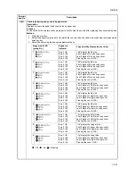
Display

Description

0

ENERGY STAR

1

GEEA

Summary of Contents for d-Copia 1600

Page 1: ...SERVICE MANUAL Published in October 2005 842HB110 First Edition d Copia 1600 d Copia 2000...

Page 2: ...sion if battery is incorrectly replaced Replace only with the same or equivalent type recommended by the manufacturer Dispose of used batteries according to the manufacturer s instructions CAUTION Dou...

Page 3: ...Revision history Revision Date Replaced pages Remarks...

Page 4: ...This page is intentionally left blank...

Page 5: ...sonnel to ensure the safety of their customers their machines as well as themselves during maintenance activities Service personnel are advised to read this booklet carefully to familiarize themselves...

Page 6: ...this symbol CAUTION Bodily injury or damage to property may result from insufficient attention to or incorrect compliance with warning messages using this symbol Symbols The triangle symbol indicates...

Page 7: ...or dusty place This may cause fire or electric shock Do not install the copier near a radiator heater other heat source or near flammable material This may cause fire Allow sufficient space around the...

Page 8: ...carefully Always check that the copier is correctly connected to an outlet with a ground connection Check that the power cable covering is free of damage Check that the power plug is dust free If it i...

Page 9: ...trapped wire and missing screws Check that all the caution labels that should be present on the machine according to the instruction handbook are clean and not peeling Replace with new ones if necess...

Page 10: ...This page is intentionally left blank...

Page 11: ...conditions 1 4 2 3 Paper misfeeds 1 4 6 1 4 2 Self diagnosis 1 4 15 1 Self diagnostic function 1 4 15 2 Self diagnostic codes 1 4 15 1 4 3 Image formation problems 1 4 20 1 No image appears entirely...

Page 12: ...the main charger unit 1 5 25 1 5 5 Developing section 1 5 26 1 Detaching and refitting the developing unit 1 5 26 1 5 6 Transfer section 1 5 27 1 Detaching and refitting the transfer roller 1 5 27 1 5...

Page 13: ...ain PWB 2 3 4 2 3 3 Engine PWB 2 3 8 2 3 4 Operation unit PWB 2 3 14 2 3 5 CCD PWB 2 3 17 2 4 Appendixes Timing chart No 1 2 4 1 Timing chart No 2 2 4 2 Timing chart No 3 2 4 3 Timing chart No 4 2 4 4...

Page 14: ...2HA 2HB 1 4 30 This page is intentionally left blank...

Page 15: ...8 sheets min B4 257 x364 mm 10 sheets min Letter 16 sheets min Letter 20 sheets min Letter R 13 sheets min Letter R 13 sheets min Ledger 8 sheets min Ledger 10 sheets min Legal 8 sheets min Legal 10 s...

Page 16: ...50 Hz 5 0 A Options Document processor paper feeder duplex unit printer board and key counter Printer functions Printing speed Same as copying speed Resolution 300 dpi 600 dpi Fast 1200 mode Standard...

Page 17: ...anel 4 Drawer 5 Width guide 6 Length guide 7 Left cover handle 8 MP tray multi purpose tray 9 Support tray 10 Slider 11 Contact glass 12 Original size indicator plate 13 Left cover 14 Waste toner box...

Page 18: ...15 Paper misfeed indicator 16 MP tray indicator 17 Copy quantity magnification display 18 Message display 19 Original size Select key 20 EcoPrint key 21 Auto Exposure key 22 Exposure adjustment keys I...

Page 19: ...ection Figure 1 1 4 Machine cross section Light path Paper path 1 Paper feed section 2 Optical section 3 Drum section 4 Developing section 5 Transfer and separation section 6 Fuser section 7 Exit and...

Page 20: ...2HA 2HB 1 4 30 This page is intentionally left blank...

Page 21: ...d air directed onto the machine Avoid dust and vibration Choose a surface capable of supporting the weight of the machine Place the machine on a level surface maximum allowance inclination 1 Avoid air...

Page 22: ...es and pins Install the original cover or the optional DP Connect the power cord Load paper Make test copies Output an own status report maintenance item U000 Exit maintenance mode Start Install the t...

Page 23: ...5 Lower left pad 6 Lower right pad 7 Upper left pad 8 Upper right pad 9 Inner frame 10 Left spacer 11 Rear spacer 12 Rear pad 13 Skid 14 Belt 15 Eject sheet 16 Machine cover 17 Bar code labels 18 Top...

Page 24: ...two pins for light source unit Figure 1 2 4 1 Install the original cover or optional DP 1 Install the optional duplex unit as necessary Install the optional paper feeder Remove the tapes and pins Tap...

Page 25: ...d shake it five times or more 5 Hold the toner container horizontally and shake it from side to side five times or more Figure 1 2 5 6 Open the front cover 7 Turn the toner container release lever and...

Page 26: ...a list of the current settings of the maintenance items 3 Press the stop clear key 1 Enter 001 using the numeric keys and press the start key The machine exits the maintenance mode 1 Place an origina...

Page 27: ...following parts Drawer heater P N 120 V specifications 2C960030 220 240 V specifications 2C960040 One 1 M4 x 10 tap tight S binding screw P N BAB54100 Procedure 1 Remove the right cover 2 Pull out the...

Page 28: ...the projections at the rear side of the cassette heater mounting plate into the two holes in the rear frame of the machine 3 Position the screw hole of the drawer heater to the screw hole of the fron...

Page 29: ...roove of the frame and put it inside the power source PWB Fit the wire into the groove so that the band mounted to the wire is located above the frame Figure 1 2 9 7 Reattach the power source PWB to i...

Page 30: ...3 bronze nut P N 7BC1003055 H01 Key counter mounting plate P N 2C960100 Key counter wire P N 2C960110 Procedure 1 Fit the key counter socket assembly to the key counter retainer using the two screws a...

Page 31: ...wire as shown in the illustra tion 6 Fold the 7 pin connector of the key counter wire back pass the wire through the clamp at the upper part of the controller box and hang it Figure 1 2 12 7 Pass the...

Page 32: ...fit the rear cover Figure 1 2 14 12 Insert the key counter into the key counter socket assembly 13 Turn the power switch on and enter the maintenance mode 14 Run maintenance item U204 and select Cnt 1...

Page 33: ...the numeric keys Enter 001 using the zoom keys or numeric keys and press the start key Enter the maintenance item number using the zoom keys or numeric keys The selected maintenance item is run Press...

Page 34: ...tment of the motor speed 0 3 0 0 5 0 1 1 3 1 5 0 5 0 1 0 3 0 3 Optical U060 Adjusting the scanner input properties 12 U061 Turning the exposure lamp on U063 Adjusting the shading position 0 U065 Adjus...

Page 35: ...se control Off U199 Checking the fuser temperature Operation panel and support equipment U200 Turning all LEDs on U202 Setting the KMAS host monitoring system U203 Operating DP separately U204 Setting...

Page 36: ...eed locations U903 Checking clearing the paper jam counts U904 Checking clearing the service call counts U905 Checking clearing counts by the DP U908 Checking the total count U910 Clearing the black r...

Page 37: ...pecify the paper feed loca tion Completion Press the stop clear key The indication for selecting a maintenance item No appears U001 Exiting the maintenance mode Description Exits the maintenance mode...

Page 38: ...r Copy quantity display Exp 1 lit 1st digit of machine number Exp 2 lit 2nd digit of machine number Exp 3 lit 3rd digit of machine number Exp 4 lit 4th digit of machine number Exp 5 lit 5th digit of m...

Page 39: ...uous copying is performed when set to 250 Copy density Keys on the operation panel other than the energy saver preheat key 5 To control the paper feed pulley remove all the paper in the drawers or the...

Page 40: ...umber of the main ROM Number of the main ROM sub Exp 1 lit Exp 2 lit Exp 3 lit Exp 4 lit Exp 5 lit Exp 1 flashing E Part Code Engine PWB Change history of the engine PWB Number of the engine ROM Numbe...

Page 41: ...between respective machines i e settings for counters service call history and mode settings As a result initializes the backup RAM according to the specifications depending on the destination select...

Page 42: ...operate correctly Method 1 Press the start key 2 Turn each switch on and off manually to check the status When the on status of a switch is detected the original size indicator corresponding to the op...

Page 43: ...the exposure adjustment keys 3 Press the start key The selected clutch turns on for 1 s Optional Completion Press the stop clear key The indication for selecting a maintenance item No appears Maintena...

Page 44: ...he start key to output a test pattern 5 Change the setting value using the zoom keys For output example 1 decrease the value For output example 2 increase the value Figure 1 3 1 6 Press the start key...

Page 45: ...copy image after the adjustment If the image is still incorrect perform the following adjustments in maintenance mode Maintenance item No Description U034 U066 P 1 3 19 U071 P 1 3 22 Exposure indicat...

Page 46: ...the image at the trailing edge or right or left side of the paper from not being copied by setting the actual size of the folio paper used Method Press the start key Setting 1 Select the item to be s...

Page 47: ...ter the value the larger the amount of slack the smaller the value the smaller the amount of slack Figure 1 3 4 6 Press the start key The value is set Completion Press the stop clear key The indicatio...

Page 48: ...nd shorter in the auxil iary scanning direction decreasing the setting makes the image shorter in the main scanning direc tion and longer in the auxiliary scanning direction 4 Press the start key The...

Page 49: ...ts 3 To turn the exposure lamp off press the stop clear key Completion Press the stop clear key The indication for selecting a maintenance item No appears U063 Adjusting the shading position Descripti...

Page 50: ...rease the value Figure 1 3 6 5 Press the start key The value is set Adjustment auxiliary scanning direction 1 Light exp 2 using the exposure adjustment key 2 Press the interrupt key 3 Place an origina...

Page 51: ...e start key 2 Press the interrupt key 3 Place an original and press the start key to make a test copy 4 Change the setting value using the zoom keys For copy example 1 decrease the value For copy exam...

Page 52: ...No appears U068 Adjusting the scanning position for originals from the DP Description Adjusts the position for scanning originals from the DP Purpose Used when there is a regular error between the le...

Page 53: ...interrupt key 3 Place an original on the DP and press the start key to make a test copy 4 Change the setting value using the zoom keys For copy example 1 increase the value For copy example 2 decrease...

Page 54: ...the setting value using the zoom keys For copy example 1 decrease the value of exp 1 For copy example 2 increase the value of exp 1 Figure 1 3 11 5 Press the start key The value is set Completion Pres...

Page 55: ...the interrupt key 3 Place an original on the DP and press the start key to make a test copy 4 Change the setting value using the zoom keys For copy example 1 increase the value For copy example 2 decr...

Page 56: ...ure amount differs significantly between when scanning an original on the contact glass and when scanning an original from the DP Method Press the start key Setting 1 Change the setting using the zoom...

Page 57: ...adjustment starts When adjustment is complete Gd appears 4 Display each setting value after adjustment using the exposure adjustment keys If a problem occurs during auto adjustment nG is displayed and...

Page 58: ...Select the item to be set using the exposure adjustment keys Setting the mode on off 1 Select on or oFF using the zoom keys Initial setting on 2 Press the start key The setting is set Setting the refe...

Page 59: ...selecting a maintenance item No appears Completion Press the stop clear key The indication for selecting a maintenance item No appears U089 Outputting a MIP PG pattern Description Selects and outputs...

Page 60: ...adjustment is complete Gd appears 4 Display each setting value after adjustment using the exposure adjustment keys If a problem occurs during auto adjustment nG is displayed and operation stops Determ...

Page 61: ...nsity larger and decreasing it makes the change smaller Figure 1 3 13 3 Press the start key The value is set Supplement While this maintenance item is being executed test copying from an original is a...

Page 62: ...th of the original is detected The scanner data taken at the nine points from 1 at the machine rear to 9 at the machine front is displayed The data is displayed within the range of 000 to 255 000 indi...

Page 63: ...osure adjustment keys Method for main charger output 1 Press the start key The selected operation starts 2 To stop operation press the stop clear key Setting the grid control voltage 1 Change the sett...

Page 64: ...the preset value Method Press the start key Setting 1 Select the group to be set or checked using the image mode selection key 2 Select the item to be set using the exposure adjustment keys Off On 3...

Page 65: ...ance item No appears Completion Press the stop clear key The indication for selecting a maintenance item No appears U130 Initial setting for the developing unit Description Executes toner install oper...

Page 66: ...Purpose To check the developing drive time after replacing the developer unit Method 1 Press the start key 2 Select the item using the exposure adjustment keys Clearing 1 Light exp 3 2 Press the start...

Page 67: ...e specified number of sheets for fuser control have passed Number of sheets for fuser control The number of sheets to be counted for switching from copying oper ation temperature 1 to copying operatio...

Page 68: ...Resetting the fuser problem data Description Resets the detection of a service call code indicating a problem in the fuser section Purpose To prevent accidents due to an abnormally high fuser tempera...

Page 69: ...perature and the absolute humidity Method 1 Press the start key 2 Display each temperature using the exposure adjustment keys Completion Press the stop clear key The indication for selecting a mainten...

Page 70: ...e stop clear key The indication for selecting a maintenance item No appears U207 Checking the operation panel keys Description Checks operation of the operation panel keys Purpose To check operation o...

Page 71: ...ication for selecting a maintenance item No appears U250 Setting the maintenance cycle Description Displays and changes the maintenance cycle Purpose To check and change the maintenance cycle Method 1...

Page 72: ...e start key Setting 1 Select the destination using the zoom keys 2 Press the start key The setting is set and the machine automatically returns to the same status as when the power is turned on Comple...

Page 73: ...lect either on or oFF using the zoom keys Initial setting on 2 Press the start key The setting is set and the indication for selecting a maintenance item No appears Completion Press the stop clear key...

Page 74: ...Setting the destination specifications Description Sets whether or not to print the product name on the reports that users print Purpose To be set according to user request Method Press the start key...

Page 75: ...for the printer using the exposure adjustment keys 2 Select on or oFF using the zoom keys 3 Press the start key The setting is set The indication for selecting a maintenance item No appears Completion...

Page 76: ...TAR If GEEA is set the Auto off mode setting is fixed to ON and cannot be changed The maximum time for entering the low power mode and the off mode becomes 120 minutes 2 Press the start key The settin...

Page 77: ...k the copy image after the adjustment If the image is still incorrect perform the following adjustments in maintenance mode Completion Press the stop clear key The indication for selecting a maintenan...

Page 78: ...value makes the margin wider and decreasing it makes the margin narrower Figure 1 3 16 6 Press the start key The value is set Completion Press the stop clear key The indication for selecting a mainten...

Page 79: ...e using the zoom keys Increasing the value makes the margin wider and decreasing it makes the margin narrower Figure 1 3 17 6 Press the start key The value is set Completion Press the stop clear key T...

Page 80: ...2 Press the interrupt key 3 Place an original and press the start key to make a test copy 4 Change the setting value using the zoom keys For copy example 1 increase the value For copy example 2 decre...

Page 81: ...tart key The counts are cleared Completion Press the stop clear key The indication for selecting a maintenance item No appears Maintenance item No Description Image mode LED group No Exposure indicato...

Page 82: ...vice call code status by types Also to clear the service call code counts after replacing con sumable parts Method 1 Press the start key 2 Display the service call code to check the count using the ex...

Page 83: ...3 Press the start key The count is cleared Clearing copy counts for all counts 1 Select group 3 2 Press the start key The counts are cleared Completion Press the stop clear key The indication for sele...

Page 84: ...black ratio data for A4 11 x 8 1 2 sheets Purpose To clear data as required at times such as during maintenance service Method 1 Press the start key 2 Select on using the zoom keys 3 Press the start k...

Page 85: ...t A4 display the A4 size First 3 digits of A4 size copy count Last 3 digits of A4 size copy count Clearing the count CLE 4 Exp 1 lit Exp 2 lit Exp 3 lit Exp 4 lit b5 display the B5 size First 3 digits...

Page 86: ...ation for selecting a maintenance item No appears Maintenance item No Description Image mode LED group No Exposure indicator Copy quantity display count value 10 Exp 1 lit Exp 2 lit Exp 3 lit Exp 4 li...

Page 87: ...Method 1 Press the start key 2 Select the item using the exposure adjustment keys Completion Press the stop clear key The indication for selecting a maintenance item No appears U941 Setting the defaul...

Page 88: ...f slack the smaller the value the smaller the amount of slack If an original non feed jam or oblique feed occurs increase the setting value If wrinkling of original occurs decrease the value 3 Press t...

Page 89: ...sing the zoom keys Initial setting 0 2 Press the start key The setting is set The indication for selecting a maintenance item No appears Setting LCD device type 1 Change the setting using the zoom key...

Page 90: ...ed time is set and the indication for selecting a maintenance item No appears Completion Press the stop clear key The indication for selecting a maintenance item No appears U991 Checking the scanner c...

Page 91: ...the start key 2 Select the VTC PG pattern to be output using the exposure adjustment keys 3 Press the interrupt key 4 Press the start key A VTC PG pattern is output Completion Press the stop clear ke...

Page 92: ...nagement mode Executing a department management item Executing a default setting item Press both of the exposure adjustment keys and manegement key for 3 s Select an item using the zoom keys or numeri...

Page 93: ...rce and press the OK key Message language Selects the language displayed on the message dis play 1 Select 02 Language and press the OK key 2 Select the language and press the OK key Original image qua...

Page 94: ...ched Letterhead Thickpaper Envelope High Quality Custom 1 8 Selected cassette Selects the cassette that is to be automatically be given priority for use 1 Select 16 DefaultCasset and press the OK key...

Page 95: ...e OK key Extra Heavy Heavy 3 Heavy 2 Heavy 1 Normal 3 Normal 2 Normal 1 Light Vellum 3 Select On or Off and press the OK key Auto detect originals Predetermines what paper size is selected for printin...

Page 96: ...uto off function is available 1 Select 51 Auto Sleep and press the OK key 2 Select On or Off and press the OK key Auto clear time Sets the auto clear time 1 Select 52 AutoClearTime and press the OK ke...

Page 97: ...n be checked in maintenance item U903 To remove paper jammed in the copier open the front cover left cover or pull the drawer out To remove original jammed in the DP open the DP original cover Paper m...

Page 98: ...2HA 2HB 1 4 2 2 Paper misfeed detection conditions Figure 1 4 2 ESW FSSW RSW PFCL RM DUPPCSW DUPFCL MPPFCL DPTSW OSBSW OCM OFM DPFCL1 DFSW1 DFSW2 DPFCL2 DPFCL3...

Page 99: ...f for 1 s and turned back on once but the switch again fails to turn on within 2560 ms 14 No paper feed from the drawer 4 third paper feeder The drawer feed switch 2 DFSW2 does not turn on within 2560...

Page 100: ...ed from first paper feeder The exit switch ESW does not turn on within 3020 ms of the registration motor RM turning on 43 Misfeed in the fuser section paper feed from second paper feeder The exit swit...

Page 101: ...ms of the duplex paper conveying switch DUPPCSW turning on The registration switch RSW does not turn off within 1760 ms of the duplex paper conveying switch DUPPCSW turning off DP 70 No original feed...

Page 102: ...tem U031 and turn registration switch on and off manually Replace registration switch if indication of switch is not light Check if the MP paper feed clutch malfunctions Run maintenance item U032 and...

Page 103: ...switch 1 actuator Check visually and replace drawer feed switch 1 if its actuator is broken Defective drawer feed switch 1 Run maintenance item U031 and turn drawer feed switch 1 on and off manually...

Page 104: ...ed in vertical paper con veying 2 Jam code 16 Broken drawer feed switch 1 or 2 actuator Check visually and replace drawer feed switch 1 or 2 if its actuator is broken Defective drawer feed switch 1 or...

Page 105: ...ctuator is bro ken Defective registration switch Run maintenance item U031 and turn registration switch on and off manually Replace registration switch if indication of switch is not light Check if th...

Page 106: ...e drawer feed switch 1 Run maintenance item U031 and turn drawer feed switch 1 on and off manually Replace drawer feed switch 1 if indication of switch is not light Broken duplex paper con veying swit...

Page 107: ...ons Run maintenance item U030 and select the exit motor to be turned on and off Check the status and remedy if necessary Electrical problem with the exit motor Check see page 1 4 26 18 A paper jam in...

Page 108: ...n and off manually Replace duplex paper conveying switch if indication of switch is not light Broken registration switch actuator Check visually and replace the registration switch if its actuator is...

Page 109: ...g switch if indication of switch is not light Check if the original con veying motor malfunctions Run maintenance item U243 and select the original conveying motor to be turned on and off Check the st...

Page 110: ...ack section is indi cated during copying An original jam in the original switch back section Jam code 75 Defective original switch back switch Run maintenance item U244 and turn original switchback sw...

Page 111: ...blem with the backup memory data Turn safety switch off and back on and run maintenance item U020 to set the contents of the backup memory data again Defective backup RAM If the C0160 is displayed aft...

Page 112: ...drawer main PWB and check for correct operation C0610 Bitmap DIMM problem There is a problem with the data or address bus of the bitmap DRAM Defective main PWB Replace the main PWB and check for cor r...

Page 113: ...blem After AGC correct input is not obtained at CCD Insufficient expo sure lamp luminos ity Replace the exposure lamp or inverter PWB Defective engine PWB Replace the engine PWB and check for cor rect...

Page 114: ...essary Broken fuser heater M or S wire Check for continuity If none replace the heater lamp C6020 Abnormally high fuser unit thermistor temperature The fuser temperature exceeds 230 C 446 F for 40 ms...

Page 115: ...WB and check for cor rect operation C7760 Drum type mismatch problem B The drum type is undefined Defective software of the engine PWB Rewrite the software of the engine PWB Defective engine PWB Repla...

Page 116: ...han the other 9 Black dots appear on the image 10 Image is blurred See page 1 4 22 See page 1 4 23 See page 1 4 23 See page 1 4 23 See page 1 4 23 11 The leading edge of the image is con sistently mis...

Page 117: ...orrect opera tion Copy example Causes Check procedures corrective measures No main charging Broken main charger wire Replace the main charger unit see page 1 5 25 Leaking main charger housing Clean th...

Page 118: ...ce the high voltage PWB and check for correct opera tion Dirty main charger wire Clean the main charger wire or if it is extremely dirty replace the main charger unit see page 1 5 25 Copy example Caus...

Page 119: ...it see page 1 5 25 Defective exposure lamp Check if the exposure lamp light is distributed evenly If not replace the exposure lamp see page 1 5 12 Copy example Causes Check procedures corrective measu...

Page 120: ...tch or registration motor installed or operating incorrectly Check the installation position and operation of the paper feed clutch MP paper feed clutch and registration motor If any of them operates...

Page 121: ...Check if the paper meets specifications Defective pressure springs Replace the pressure springs Flawed press roller Replace the press roller see page 1 5 30 Defective fuser heater Replace the fuser he...

Page 122: ...rive motor YC7 5 on the engine PWB Registration motor YC2 1 2 4 5 on the registration motor PWB Exit motor YC14 1 2 3 4 on the engine PWB Defective engine PWB Run maintenance item U030 and check if fo...

Page 123: ...heater M or S Check for continuity across each heater If none replace the heater M or S Fuser thermostat triggered Check for continuity across thermostat If none remove the cause and replace the ther...

Page 124: ...aper in the drawer is not dis played correctly Poor contact in the paper length switch connector ter minals Reinsert the connector Also check for continuity within the con nector cable If none remedy...

Page 125: ...Repair or replace 4 The scanner does not travel Check if the scanner wire is loose Reinstall the scanner wire see page 1 5 13 The scanner motor malfunctions See page 1 4 26 5 Multiple sheets of paper...

Page 126: ...2HA 2HB 1 4 30 This page is intentionally left blank...

Page 127: ...ute electric wires as the copier may be seri ously damaged 2 Drum Note the following when handling or storing the drum When removing the drum unit never expose the drum surface to strong direct light...

Page 128: ...he start key Enter the maintenance item number using the zoom keys or numeric keys The selected maintenance item is run Press the stop clear key Press the start key Start End Maintenance mode is enter...

Page 129: ...ce the separation pulley Procedure 1 Open the front cover and left cover Remove the waste toner box 2 Pull out the drawer Figure 1 5 1 3 Remove the screw and then the front left lower cover Figure 1 5...

Page 130: ...ey unit from the lower paper feed unit 6 Remove the separation pulley from the sep aration pulley unit 7 Replace the separation pulley and refit all the removed parts Figure 1 5 4 Separation pulley Lo...

Page 131: ...wer paper feed unit see page 1 5 3 2 Remove the drum unit see page 1 5 23 3 Remove the rear cover 4 Remove the paper feed clutch stop ring and bushing at the machine rear Figure 1 5 5 5 Remove the scr...

Page 132: ...8 Remove the forwarding pulley from the upper paper feed unit 9 Remove the paper feed pulley from the upper paper feed unit 10 Replace the forwarding pulley and paper feed pulley and refit all the rem...

Page 133: ...r side Restore the paper conveying unit Remove the pin and plate and then remove the stopper from the front side 3 Open the left cover until it is put horizontally Figure 1 5 10 4 Push the fitting por...

Page 134: ...Remove the MP upper cover from the MP unit Figure 1 5 12 7 Detach the connector and remove the MP lower cover from the copier Figure 1 5 13 8 Remove the paper conveying unit from the copier Figure 1 5...

Page 135: ...e toner box Pull out the drawer 2 Remove the screw and then the front left lower cover Figure 1 5 15 3 Remove the paper conveying unit see page 1 5 7 4 Remove the stop ring and bushing at the machine...

Page 136: ...e MP paper feed pulley from the MP paper feed pulley shaft Figure 1 5 19 9 Push the fitting portions of the MP separa tion pad Remove the MP separation pad from the copier 10 Replace the MP paper feed...

Page 137: ...4 Replace the registration left roller and refit all the removed parts Figure 1 5 21 6 Detaching and refitting the registration cleaner Follow the procedure below to replace the registration cleaner P...

Page 138: ...glass Figure 1 5 24 3 Move the mirror 1 frame to the cutouts of the machine When moving the mirror 1 frame do not touch the exposure lamp nor the inverter PWB 4 Detach the exposure lamp connector fro...

Page 139: ...Remove the two screws holding the middle left cover and upper left cover and then the covers Figure 1 5 27 3 Remove the screw and then the slit retainer and slit glass Detach the fitting portions and...

Page 140: ...1 frame from the scanner unit Figure 1 5 30 6 Unhook the round terminal of the scanner wire from the scanner tension spring on the left side of the scanner unit 7 Remove the scanner wire Figure 1 5 3...

Page 141: ...g tools Two frame securing tools P N 302C968310 Two scanner wire stoppers P N 3596811 Procedure 1 Remove the screw and then scanner wire drum gear at the machine rear side Figure 1 5 32 2 Remove the s...

Page 142: ...utward 5 Secure the scanner wires using the scanner wire stoppers Figure 1 5 34 6 Refit the scanner wire drum shaft to the scanner unit 7 Insert the two frame securing tools into the positioning holes...

Page 143: ...f the scanner unit 5 13 Hook the round terminals onto the scanner tension springs 6 Figure 1 5 36 14 Remove the scanner wire stoppers and frame securing tools 15 Gather the scanner wires toward the lo...

Page 144: ...Detach the CCD wire from the CCD PWB 4 Remove the four screws holding the ISU and then the ISU 5 Replace the ISU Figure 1 5 39 Refitting the ISU 1 Align the positioning holes of the ISU by pushing it...

Page 145: ...per rear cover middle left cover upper left cover slit glass and front scanner cover see page 1 5 13 3 Remove the four screws holding the right cover and then the cover Remove the ten screws holding t...

Page 146: ...43 6 Remove the screw holding the exit cover and then the cover Remove the two screws holding the inner rear cover and then the cover Figure 1 5 44 7 Remove the front and rear left cover Figure 1 5 4...

Page 147: ...ittle Figure 1 5 46 9 Remove the exit tray Figure 1 5 47 10 Remove the four screws and detach the two connector and then remove the laser scan ner unit 11 Replace the laser scanner unit and refit all...

Page 148: ...crews and refit the contact glass 5 Adjusting the longitudinal squareness reference Perform the following adjustment if the copy image is longitudinally skewed longitudinal squareness not obtained Cau...

Page 149: ...ocedure 1 Open the front cover and left cover Remove the waste toner box and toner container 2 Remove the inner cover 3 Remove the screw holding the developing release lever 4 Pull the developing rele...

Page 150: ...aration claws Procedure 1 Remove the drum unit see page 1 5 23 2 Push the drum separation claws with the minus driver from the top of the corner hole and remove the claws 3 Replace the drum separation...

Page 151: ...rger unit toward the upper right remove the unit from the copier 3 While pressing the main charger release lever in the direction indicated by the arrow at the removal stopper position to release the...

Page 152: ...unit Follow the procedure below to replace the developing unit Procedure 1 Remove the drum unit see page 1 5 23 2 While lifting the developing unit a little remove the unit from the copier 3 Replace t...

Page 153: ...and rear release lever stoppers and then the stoppers from the release lever shaft Figure 1 5 56 3 Detach the fitting portions located on the front and rear and then remove the transfer roller from t...

Page 154: ...de screwdriver or the like through the groove at the left side of the machine and unlock the engaged portion of front left cover 1 to remove it Figure 1 5 58 3 Remove the screw and then remove the fro...

Page 155: ...2HA 2HB 1 5 29 5 Remove the screw and detach the two con nectors and then remove the fuser unit from copier 6 Replace the fuser unit and refit all the removed parts Figure 1 5 61 Fuser unit Connectors...

Page 156: ...s and then separate the fuser right unit and left unit Figure 1 5 62 3 Remove the three screws holding the press roller guide from fuser right unit Figure 1 5 63 4 Remove the press roller from the fus...

Page 157: ...nit and left unit see pages 1 5 28 30 2 Remove the two screws holding each of the fuser heater M and S on the front and rear of the fuser left unit Figure 1 5 65 3 Pull out the fuser heater M and S fr...

Page 158: ...e fuser right unit and left unit see page 1 5 28 30 2 Detach the fitting portions and then remove the heat roller guide from the fuser left unit Figure 1 5 67 3 Remove the heat roller separation claws...

Page 159: ...parate the fuser right unit and left unit see pages 1 5 28 30 2 Remove the heat roller separation claws see page 1 5 32 3 Pull out the heat roller bushing from the fuser left unit and then remove the...

Page 160: ...the thermostat 4 Replace the fuser thermostat and refit all the removed parts Figure 1 5 70 7 Detaching and refitting the fuser thermistor Follow the procedure below to replace the fuser thermistor P...

Page 161: ...fuser unit on the third step from the bottom of the spacer to adjust the spacer position height adjust ment of 0 5 mm In the case of copy example 2 the trailing edge of image of the machine front side...

Page 162: ...2HA 2HB 1 4 30 This page is intentionally left blank...

Page 163: ...e right side 4 Insert the DIMM into the DIMM slot on the main PWB Insert the power plug and turn the power switch on 5 Upgrading firmware starts and the status is displayed on the operation panel 6 Wh...

Page 164: ...age PWB VR201 VR202 VR301 Drum unit zener PWB VR1 1 6 3 Remarks on PWBs replacement Confirm the version of the firmware and upgrade the version in up to date state when replacing PWBs When replacing t...

Page 165: ...the drawer by the rotation of the forwarding pulley and paper feed pulley The separation pulley prevents multiple sheets from being fed at one time via the torque limiter The MP tray can hold up to 5...

Page 166: ...DPWB YC4 4 YC8 9 YC8 3 YC8 5 YC8 2 YC8 8 YC1 4 YC1 9 YC1 15 YC1 13 YC1 16 YC1 10 YC2 1 2 4 5 YC5 12 YC2 2 YC3 1 YC6 2 YC5 9 YC22 1 2 4 PFCL PFCL RM RM RSW RSW PSW PSW PLSW PLSW MPPFCL MPPFCL MPPWSW MP...

Page 167: ...and the laser scanner unit for printing Figure 2 1 3 Optical section 1 Mirror 1 frame 2 Mirror 2 frame 3 Exposure lamp EL 4 Mirror 1 5 Mirror 2 6 Mirror 3 7 Image scanning unit ISU 8 CCD PWB CCDPWB 9...

Page 168: ...t and rear of the machine to scan from side to side The speed of the mirror frames is half the speed of the scanner When the DP is used the scanner and mirror frames stop at the DP original scanning p...

Page 169: ...Polygon motor Drives the polygon mirror 6 F lens Corrects for non linearity of the laser beam scanning speed on the drum surface keeps the beam diameter constant and corrects for the vertical alignmen...

Page 170: ...a static latent image on the drum The static latent image of the letter A for example is formed on the drum surface as shown in Figure 2 1 7 Electrical charge is dissipated on the area of the drum su...

Page 171: ...section consists of the cleaning blade and cleaning roller that removes residual toner from the drum surface after the transfer process and the cleaning spiral that carries the residual toner back to...

Page 172: ...s formed the doctor blade and the develop ing spirals that agitate the toner Also the toner container sensor TCS checks whether or not toner remains in the toner container Figure 2 1 10 Developing sec...

Page 173: ...the position of the poles on the mag net roller and the position of the doctor blade A developing bias voltage generated by the high voltage PWB HVTPWB is applied to the developing roller to provide i...

Page 174: ...eveloping sleeve by an electric field of the magnetic pole Then when the developing sleeve rotates and passes through the nearest location to the drum on the portion of the drum that has been exposed...

Page 175: ...ging Paper after transfer is separated from the drum by applying separation bias that is output from the high voltage PWB HVTPWB to the separation electrode Figure 2 1 14 Transfer and separation secti...

Page 176: ...ther mistor FTH and is regulated by the fuser heaters turning on and off If the fuser section becomes abnormally hot fuser thermostat FTS operates shutting the power to the fuser heaters off When the...

Page 177: ...t motor In duplex copying paper is turned over by reverse rotation of the exit motor Figure 2 1 18 Exit and switchback sections Figure 2 1 19 Exit and switchback sections block diagram 1 Feedshift gui...

Page 178: ...is then conveyed to the copier paper feed section by the upper and lower duplex feed rollers Figure 2 1 20 Duplex section Figure 2 1 21 Duplex section block diagram 1 Duplex feed pulley 2 Upper duplex...

Page 179: ...duplex unit via the exit roller and the switchback roller Paper that has been conveyed to the duplex unit is conveyed to the paper feed section again by rotation of the upper duplex feed roller and t...

Page 180: ...2HA 2HB 1 4 30 This page is intentionally left blank...

Page 181: ...voltages for separation 5 Inverter PWB INPWB Controls the exposure lamp 6 CCD PWB CCDPWB Reads the image off originals 7 Operation unit PWB OPWB Consists of the operation keys and display LEDs 8 Draw...

Page 182: ...ch ODSW Operates the original size detection sensor 10 Original size detection sensor OSDS Detects the size of the original 11 Registration switch RSW Controls the secondary paper feed start timing 12...

Page 183: ...al system 3 Exit motor EM Drives the exit section 4 Cooling fan motor 1 CFM1 Cools the machine interior 5 Cooling fan motor 2 CFM2 Cools the machine interior 6 Polygon motor PM Drives the polygon mirr...

Page 184: ...Exposes originals 4 Cleaning lamp CL Removes residual charge from the drum surface 5 Fuser heater M FH M Heats the heat roller 6 Fuser heater S FH S Heats the heat roller 7 Fuser thermostat FTS Preve...

Page 185: ...heater control circuit IL001 FG DH1 LIVE DH2 LIVE DH1 OUT DH2 OUT SH OUT Fuser heater ON OFF circuit MH OUT AC INPUT TR001 TR002 Fuser heater control circuit Zero cross circuit Rectifier circuit Ener...

Page 186: ...C2 1 5 V O 5 V DC power supply for EPWB Connected to the engine PWB 2 SGND Ground 3 24 V2 I 24 V DC power supply 4 SGND Ground 5 ZCROSS O Zero cross signal 6 SLEPN I Power source sleep signal 7 S HEAT...

Page 187: ...O AC power supply for drawer heater of the paper feeder LIVE Connected to the optional paper feeder 2 NC Not used 3 NC Not used 4 DH2 OUT O AC power supply for drawer heater of the paper feeder YC8 1...

Page 188: ...DYN SCKN EGSI EGSO KYE SCAN LEDON LCDD LCDRS LCDEN LCDR_W SBSY SDIR EGIRN RSTN EGSO SCKN EGSI OVSYNK PDMASKN SAMPLE VDATAN OUTPEN PDN PLGCLK EGIRN SBSY SDIR RSTN OUTPEN PDN VDATAN SAMPLE LSU ASIC1 CPU...

Page 189: ...1 1 1 100 72 1 13 1 1 10 A1 22 1 1 12 A30 B1 B30 16 1 1 1 18 5 17 18 U5 U6 U7 U32 U33 U1 U30 U21 U2 U36 U10 U11 U3 X1 X2 U18 X3 U31 U22 U14 U16 U25 U12 U28 U34 U29 U35 U27 U26 U24 U8 U9 U20 U19 U17 U...

Page 190: ...D Ground 16 SGND Ground YC6 1 LED0 O LED lighting selection signal 0 Connected to the opera tion unit PWB 2 LED1 O LED lighting selection signal 1 3 LED2 O LED lighting selection signal 2 4 LED3 O LED...

Page 191: ...D PWB 2 CCDON I CCDPWB image scanning signal 3 CCDE Ground 4 CCDEN I CCDPWB image scanning signal 5 5 V O 5 V DC power supply for CCDPWB 6 SGND Ground 7 12 V O 12 V DC power supply for CCDPWB 8 SGND G...

Page 192: ...SEL0L LOPSEL1N LOPSEL2N LOPSRDY DHVCLK DB DHVIADJ THVIADJ ILOCKF ILOCKL ERASE1N ERASE2N THERMA ZCROSS TCS OFS HUMID Duplex unit Fuser unit RM Paper feeder LSU CPU ASIC MPWB Scanner unit DP INPWB CCD P...

Page 193: ...6 1 1 2 1 16 1 1 1 1 1 1 1 2 1 1 1 1 1 4 1 1 2 1 13 4 14 1 3 7 13 2 4 1 11 14 4 7 2 5 4 6 1 1 3 1 12 6 1 YC4 YC12 YC25 U17 YC5 YC15 YC14 YC3 YC7 YC27 YC23 YC10 YC20 YC24 YC13 YC2 YC21 YC11 U13 YC17 Y...

Page 194: ...3 1 PLGCLKN O PM clock signal Connected to the poly gon motor cleaning lamp cool ing fan motor 1 and overflow sensor 2 PLGRDYN I PM rotation sync signal 3 PLGDRN O PM on off 4 PLGGND Ground 5 PLG 24 V...

Page 195: ...B 3 SHVISELN O Separation high voltage switch signal 4 PGND Ground 5 MHVDRN O Main charging high voltage on off 6 PGND Ground 7 SHVDRN O Separation high voltage on off 8 PGND Ground 9 MHVADJ O Main ch...

Page 196: ...C17 1 LAMPN O EL on off Connected to the inverter PWB 2 PGND Ground 3 24 V1 O 24 V DC power supply for inverter PWB 4 24 V1 O 24 V DC power supply for inverter PWB 5 PGND Ground 6 LAMPN O EL on off YC...

Page 197: ...SW3N I PLSW on off Connected to the paper size length switch and toner con tainer detec tion switch 2 C1PLSW2N I PLSW on off 3 SGND Ground 4 C1PLSW1N I PLSW on off 5 TCONDET I TCDSW on off 6 SGND Grou...

Page 198: ...6N SCAN5N SCAN4N SCAN3N SCAN2N SCAN1N SCAN0N 10 9 8 7 6 5 4 3 2 1 f1 f2 f3 g1 g2 g3 DP1 DP2 DP3 Dig1 Dig1 Dig2 Dig3 27 23 17 28 22 12 5 9 14 3 26 19 18 e3 e2 e1 d3 d2 d1 c3 c2 c1 b3 b2 b1 a3 a2 a1 10...

Page 199: ...K19 K12 K9 K15 K18 K13 YC2 YC2 K14 K11 K39 K6 K5 K8 K7 K10 K3 K1 K4 K2 L1 L8 L5 L2 L6 L7 L15 L16 L75 L9 L10 L11 L12 L44 L45 L46 L74L73 L71L70 L69 L72 L28 L36 L37 L29 L20 L21 L22 L18 L17 L27 L26 L19 L...

Page 200: ...main PWB 2 KEY3 O Key switch return signal 3 3 KEY2 O Key switch return signal 2 4 KEY1 O Key switch return signal 1 5 KEY0 O Key switch return signal 0 6 LED12 I LED lighting selection signal 12 7 LE...

Page 201: ...2HA 2HB 2 3 17 2 3 5 CCD PWB Figure 2 3 9 CCD PWB block diagram Figure 2 3 10 CCD PWB silk screen diagram MPWB Tr AMP Driver CCD sensor U2 U1 U3 CCDPWB U1 U2 U3 U4 YC1...

Page 202: ...CP signal 5 SGND Ground 6 RS I MPWB RS signal 7 SGND Ground 8 CCDCLKN I CCDCLKN signal 9 SGND Ground 10 CCDCLK I CCDCLK signal 11 SGND Ground 12 12 V I 12 V DC power supply from MPWB 13 SGND Ground 14...

Page 203: ...ode original size A4 11 x 8 1 2 two sheets PFCL 125 ms 125 ms RSW RM Dev BIAS ESW YC8 3 YC8 9 YC4 4 YC9 7 YC9 11 YC15 2 430 ms 430 ms 330 ms 200 ms 350 ms 350 ms 370 ms 420 ms 2020 ms 1900 ms Primary...

Page 204: ...two sheets PFCL 125 ms 125 ms 4000 ms 4000 ms RSW RM Dev BIAS ESW 430 ms 430 ms 330 ms 200 ms 350 ms 350 ms 370 ms 370 ms 420 ms 420 ms 2020 ms 200 ms 330 ms 2020 ms YC8 3 YC8 9 YC4 4 YC9 7 YC9 11 YC...

Page 205: ...riginal size A4 11 x 8 1 2 two sheets DPFCL1 Optional 120 ms 120 ms RSW RM YC8 9 YC4 4 DDM1 ESW 82 ms 200 ms 820 ms 1780 ms 1900 ms 1780 ms 82 ms 350 ms 350 ms 370 ms 420 ms 2020 ms YC9 7 YC9 11 YC15...

Page 206: ...8 1 2 two sheets DPFCL2 300 ms 300 ms 120 ms 120 ms DDM1 RSW DDM2 1560 ms 1340 ms 1340 ms 1560 ms 1140 ms 1900 ms 200 ms 82 ms 82 ms 350 ms 350 ms 370 ms 420 ms 2020 ms ESW RM DFSW1 YC8 9 YC9 7 YC9 1...

Page 207: ...ns LENS Reflector REFLECTOR SCANNER 2C912110 8 12 Exposure lamp LAMP SCANNER YG 2C912090 8 10 Front scanner rail FRONT RAIL SCANNER Rear scanner rail REAR RAIL SCANNER Original size detection sensor S...

Page 208: ...ical section Slit glass Clean Every 150 000 counts Clean with a dry cloth Contact glass Clean Every 150 000 counts Clean with alcohol and then a dry cloth Mirror 1 Clean Clean with a wet cloth and the...

Page 209: ...5 33 Press roller Clean Every 150 000 counts Clean with alcohol or a dry cloth P 1 5 30 Heat roller separation claw Clean or replace Every 150 000 counts Clean with alcohol Replace if it is being lac...

Page 210: ...sting the leading edge registra tion of the MP tray printing adjust ment Registration motor turning on timing sec ondary paper feed start timing U034 Exp 2 light U034 test pattern P 1 3 12 Adjusting t...

Page 211: ...glass U071 For copying originals from the DP Adjusting the leading edge margin scanning adjustment Adjusting the original scan data image adjustment U403 U404 Exp 2 light Exp 2 light Test chart P 1 3...

Page 212: ...2 1 CL 1 2 3 R G 3 2 1 TONEGND TONEFUL TONE 5V2 8 9 10 1 2 2 1 FAN1DRN 24V1 THERMA THERMA 5V YC14 4 3 2 1 COMDB COMDNA COMDNB COMDA 5V OUT1 OUT2 GND 2 1 GY GY 1 2 7 6 5 4 3 1 2 3 4 5 1 2 3 4 2 1 6 7...

Page 213: ...INSTALLATION GUIDE FOR THE 300 SHEET CASSETTE...

Page 214: ...sadores de ubicaci n 1 en la parte trasera del casete A Cuando coloque la copiadora h galo con cuidado para no golpear el cuerpo principal contra la gaveta los pasadores o la placa de fondo del casete...

Page 215: ...go para los modelos MFP de 20 ppm puede apilar hasta dos casetes 2 Si se utiliza un tipo de papel no incluido en las especificaciones para el tama o de casete de hoja normal cambie la indicaci n de la...

Page 216: ...er casete opcional Presione la tecla de exposici n hasta que se encienda exp5 modo 5 Haga una copia de prueba para verificar la imagen Si no puede obtenerse una imagen adecuada realice el siguiente aj...

Page 217: ...r casete opcional Presione la tecla de exposici n hasta que se encienda exp5 modo 5 Haga una copia de prueba para verificar la imagen Si no puede obtenerse una imagen adecuada realice el siguiente aju...

Page 218: ...io de valor en una unidad mueve el extremo gu a en 0 1 mm 3 Haga salir nuevamente el patr n de prueba 4 Repita los pasos 2 y 3 hasta que se obtenga una imagen adecuada Falls Sie ein Bild des Typs c er...

Page 219: ...d mueve la l nea de centro en 0 1 mm 3 Haga salir nuevamente el patr n de prueba 4 Repita los pasos 2 y 3 hasta que se obtenga una imagen adecuada Falls Sie ein Bild des Typs c erhalten verringern Sie...

Page 220: ...INSTALLATION GUIDE FOR THE DOCUMENT PROCESSOR...

Page 221: ...P de bronce M3 x 06 2 FEtiqueta de precauci n 1 GPlaca de protecci n del conector 1 Procedimiento 1 Si se instal el soporte original desm ntelo y saque los dos tornillos 1 de la cubierta superior tras...

Page 222: ...lado delantero 4 Asegure el DP A con los dos tornillos cromado Taptite TP M4 x 10 C y los dos tornillos 1 quitados en el paso 1 5 Cierre el DP A introduciendo el herraje de fijaci n D del lado trasero...

Page 223: ...del connettore G nel pannello posteriore a mezzo della vite 4 La piastra di protezione del connettore G non utilizzata per la copiatrice MFP 8 F F DP A F 8 Clean the pasting position for the label in...

Page 224: ...originales y caj n al tama o de papel a utilizar 3 Si la imagen de la copia con coincide con la imagen del original realice los siguientes ajustes en el modo de mantenimiento Modo de mantenimiento 070...

Page 225: ...inuye el valor Para un ejemplo de copia e aumenta el valor Un cambio de valor en una unidad cambia la l nea de exploraci n secundaria en 0 1 A mayor valor mayor es la amplificaci n de la l nea de expl...

Page 226: ...tremo gu a Original a Para un ejemplo de copia f aumenta el valor Para un ejemplo de copia g disminuye el valor Un cambio de valor en una unidad mueve el extremo gu a en 0 17 mm A mayor valor m s tard...

Page 227: ...line adjustment Original a For copy example h increase the value For copy example i decrease the value Changing the value by one moves the center line by 0 17 mm The larger the value the center of th...

Page 228: ...eispiel e Erh hen Sie den Wert Einstellbereich 25 25 Durch ndern des Werts um eins wird die Nebenscanlinie um 0 1 ver ndert Ein kleinerer Einstellwert macht das Kopienbild k rzer Ein gr erer Wert mach...

Page 229: ...el modo de mantenimiento 071 Seleccione LEAD1 Para el ajuste del lado trasero en el copiado duplex seleccione LEAD2 Coloque los originales en la bandeja de originales y presione la tecla de interrupc...

Page 230: ...ado duplex seleccione 2sided front Para el ajuste del lado trasero seleccione 2sided back Coloque los originales en la bandeja de originales y presione la tecla de interrupci n Haga una copia de prueb...

Page 231: ...INSTALLATION GUIDE FOR THE DUPLEX UNIT...

Page 232: ...hufe del recept culo de pared antes de empezar a instalar la Unidad D plex 1 Abra la cubierta izquierda 1 2 Desmonte el anillo de tope 2 y la correa 3 del lado trasero 3 Recupere la secci n del transp...

Page 233: ...de cable 4 de la unidad duplex A en el sentido indicado por la flecha 7 Inserte las secciones de eje 5 de la unidad duplex A en las ranuras en forma de U de la unidad transportadora 8 Presione la unid...

Page 234: ...n 12 Die entfernten Teile wieder an ihren urspr nglichen Positionen anbringen 13 Den Netzstecker der Haupteinheit an die Netzsteckdose anschlie en und den Hauptschalter der Haupteinheit einschalten 10...

Page 235: ...rificar la imagen Si no puede obtenerse una imagen adecuada realice el siguiente ajuste 2 a Imagen adecuada Si se obtiene una imagen de tipo b aumente el valor del ajuste Si se obtiene una imagen de t...

Page 236: ...rificar la imagen Si no puede obtenerse una imagen adecuada realice el siguiente ajuste 2 a Imagen adecuada Si se obtiene una imagen de tipo b aumente el valor del ajuste Si se obtiene una imagen de t...

Page 237: ...ende Einstellung aus 2 a Einwandfreies Bild Falls Sie ein Bild des Typs b erhalten erh hen Sie den Einstellwert Se il tipo di pannello operativo quello LCD Regolazione della sincronizzazione del bordo...

Page 238: ...g aus 2 a Einwandfreies Bild Falls Sie ein Bild des Typs b erhalten erh hen Sie den Einstellwert Se il tipo di pannello operativo quello LCD Regolazione della linea di centro 1 Avviare il modo manuten...

Page 239: ...INSTALLATION GUIDE FOR THE Printing System X...

Page 240: ...desenchufe la fotocopiadora del suministro el ctrico Instalaci n de la tarjeta de impresora 1 Quite los dos tornillos 1 y desmonte la cubierta 2 2 Inserte la tarjeta de impresora A completamente en l...

Page 241: ...n 1 Den mit Ferritkern versehenen Stecker des mit IB 110 gelieferten Netzkabels E an die Druckerkarte und das andere Ende an IB 110 anschlie en 2 Das mit IB 110 gelieferte USB Kabel F an die Druckerka...

Page 242: ......

Reviews: