2HA/2HB
1-2-12
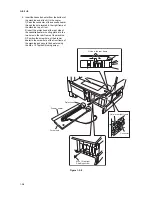
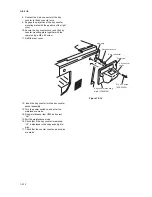
8. Connect the 4-pin connector of the key
counter to the key counter wire.
9. Engage the projection of the key counter
mounting plate with the aperture of the right
cover.
10. Secure the key counter cover and the key
counter mounting plate together with the
copier using a M4 x 40 screw.
11. Refit the rear cover.
Figure 1-2-14
12. Insert the key counter into the key counter
socket assembly.
13. Turn the power switch on and enter the
maintenance mode.
14. Run maintenance item U204 and select
“Cnt”.
15. Exit the maintenance mode.
16. Check that if the key counter is removed,
“U1” is displayed in the copy quantity dis-
play.
17. Check that the counter counts up as copies
are made.
Key counter wire
4-pin connector
Aperture
Key counter
cover
Key counter mounting
plate (2C960100)
M4 x 40 screw
(B1B54400)
Projection
Summary of Contents for d-Copia 1600
Page 1: ...SERVICE MANUAL Published in October 2005 842HB110 First Edition d Copia 1600 d Copia 2000...
Page 3: ...Revision history Revision Date Replaced pages Remarks...
Page 4: ...This page is intentionally left blank...
Page 10: ...This page is intentionally left blank...
Page 14: ...2HA 2HB 1 4 30 This page is intentionally left blank...
Page 20: ...2HA 2HB 1 4 30 This page is intentionally left blank...
Page 126: ...2HA 2HB 1 4 30 This page is intentionally left blank...
Page 162: ...2HA 2HB 1 4 30 This page is intentionally left blank...
Page 180: ...2HA 2HB 1 4 30 This page is intentionally left blank...
Page 213: ...INSTALLATION GUIDE FOR THE 300 SHEET CASSETTE...
Page 220: ...INSTALLATION GUIDE FOR THE DOCUMENT PROCESSOR...
Page 231: ...INSTALLATION GUIDE FOR THE DUPLEX UNIT...
Page 239: ...INSTALLATION GUIDE FOR THE Printing System X...
Page 242: ......


