2HA/2HB
2-3-1
2-3 Operation of the PWBs
2-3-1 Power source PWB
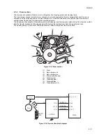
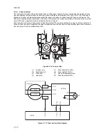
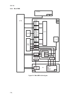
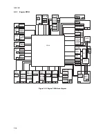
Figure 2-3-1 Power source PWB block diagram
The power source PWB (PSPWB) is a switching regulator that converts an AC input to generate 24 V DC and 5 V DC. It
includes a rectifier circuit, a switching regulator circuit, a 24 V DC output circuit, a 5 V DC output circuit, overvoltage detec-
tion circuit, zero-cross circuit and a fuser heater control circuit.
IL001
FG
DH1.LIVE
DH2.LIVE
DH1.OUT
DH2.OUT
SH.OUT
Fuser heater
ON/OFF circuit
MH.OUT
AC
INPUT
(TR001,TR002)
Fuser heater
control circuit
Zero-cross circuit
Rectifier circuit
Energy save control circuit
PC001
D101
D005
T001
L004
L003
F002
F001
F003
SW001
C102
F201
C008
C204
Q006
D206
PC002
PC004
PC005
PC003
AC
detection
circuit
Zero-cross
output circuit
ON/OFF
switch circuit
+24V
GND
GND
+5V
+5V1
ZCROSS
S.HEATN
M.HEATN
SLEPN
Switching
control circuit
(IC001)
Overvoltage
detection circuit
DC5V
output
circuit
DC5V
3 terminal
regulator
DC24V
output
circuit
(IC201)
(IC301)
Summary of Contents for d-Copia 1600
Page 1: ...SERVICE MANUAL Published in October 2005 842HB110 First Edition d Copia 1600 d Copia 2000...
Page 3: ...Revision history Revision Date Replaced pages Remarks...
Page 4: ...This page is intentionally left blank...
Page 10: ...This page is intentionally left blank...
Page 14: ...2HA 2HB 1 4 30 This page is intentionally left blank...
Page 20: ...2HA 2HB 1 4 30 This page is intentionally left blank...
Page 126: ...2HA 2HB 1 4 30 This page is intentionally left blank...
Page 162: ...2HA 2HB 1 4 30 This page is intentionally left blank...
Page 180: ...2HA 2HB 1 4 30 This page is intentionally left blank...
Page 213: ...INSTALLATION GUIDE FOR THE 300 SHEET CASSETTE...
Page 220: ...INSTALLATION GUIDE FOR THE DOCUMENT PROCESSOR...
Page 231: ...INSTALLATION GUIDE FOR THE DUPLEX UNIT...
Page 239: ...INSTALLATION GUIDE FOR THE Printing System X...
Page 242: ......

