2HA/2HB
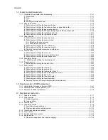
2-2 Electrical Parts Layout
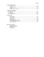
2-2-1 Electrical parts layout..............................................................................................................................2-2-1
(1) PWBs ................................................................................................................................................2-2-1
(2) Switches and sensors .......................................................................................................................2-2-2
(3) Motors ...............................................................................................................................................2-2-3
(4) Other electrical components..............................................................................................................2-2-4
2-3 Operation of the PWBs
2-3-1 Power source PWB.................................................................................................................................2-3-1
2-3-2 Main PWB ...............................................................................................................................................2-3-4
2-3-3 Engine PWB............................................................................................................................................2-3-8
2-3-4 Operation unit PWB ..............................................................................................................................2-3-14
2-3-5 CCD PWB .............................................................................................................................................2-3-17
2-4 Appendixes
Timing chart No.1....................................................................................................................................2-4-1
Timing chart No.2....................................................................................................................................2-4-2
Timing chart No.3....................................................................................................................................2-4-3
Timing chart No.4....................................................................................................................................2-4-4
Maintenance parts list .............................................................................................................................2-4-5
Periodic maintenance procedures ..........................................................................................................2-4-6
Chart of image adjustment procedures...................................................................................................2-4-8
General wiring diagram.........................................................................................................................2-4-10
INSTALLATION GUIDE
300-SHEET CASSETTE
DOCUMENT PROCESSOR
DUPLEX UNIT
Printing System (X)
Summary of Contents for d-Copia 1600
Page 1: ...SERVICE MANUAL Published in October 2005 842HB110 First Edition d Copia 1600 d Copia 2000...
Page 3: ...Revision history Revision Date Replaced pages Remarks...
Page 4: ...This page is intentionally left blank...
Page 10: ...This page is intentionally left blank...
Page 14: ...2HA 2HB 1 4 30 This page is intentionally left blank...
Page 20: ...2HA 2HB 1 4 30 This page is intentionally left blank...
Page 126: ...2HA 2HB 1 4 30 This page is intentionally left blank...
Page 162: ...2HA 2HB 1 4 30 This page is intentionally left blank...
Page 180: ...2HA 2HB 1 4 30 This page is intentionally left blank...
Page 213: ...INSTALLATION GUIDE FOR THE 300 SHEET CASSETTE...
Page 220: ...INSTALLATION GUIDE FOR THE DOCUMENT PROCESSOR...
Page 231: ...INSTALLATION GUIDE FOR THE DUPLEX UNIT...
Page 239: ...INSTALLATION GUIDE FOR THE Printing System X...
Page 242: ......


