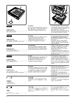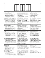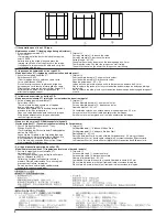
付属品
A
DP本体 ................................................................ 1
B
ピン ...................................................................... 2
C
TPタップタイトクロメートビスM4x10 ....... 2
D
固定金具 .............................................................. 1
E
TPブロンズビスM3x06 .................................. 2
F
注意ラベル .......................................................... 1
G
コネクタ保護金具 ............................................... 1
1
A
B
D
F
G
C
E
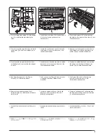
[取付手順]
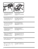
1. 原稿押さえが取り付けられている場合は、
原稿押さえを取り外し、後上カバーのビス
1
2本を外す。
2. ピン
B
2本を後上カバーのビス穴に通して
下フレームに取り付ける。
1
1
B
B
Supplied parts
A
DP main body ........................................... 1
B
Pin ............................................................ 2
C
TP Taptite chromate screw M4 x 10 ......... 2
D
Fixing fitting .............................................. 1
E
Bronze TP screw M3 x 06 ........................ 2
F
Caution label ............................................. 1
G
Connector protecting plate ....................... 1
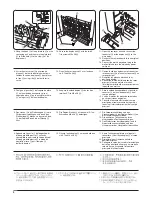
Procedure
1. If the original holder is attached, remove it
and remove the two screws
1
from the top
rear cover.
2. Pass the two pins
B
through the screw
holes of the rear top cover and attach them
to the lower frame.
Pièces fournies
A
Corps principal du DP ............................... 1
B
Goupille .................................................... 2
C
Vis chromée taptite TP M4 x 10 ............... 2
D
Fixation ..................................................... 1
E
Vis TP en bronze M3 x 06 ........................ 2
F
Étiquette d'avertissement ......................... 1
G
Plaque de protection du connecteur ......... 1
Procédure
1. Si le support d'original est fixé, le retirer et
retirer les deux vis
1
du couvercle
supérieur arrière.
2. Faites passer les deux goupilles
B
par les
trous de vis du couvercle supérieur arrière
et fixez-les au cadre inférieur.
Piezas suministradas
A
Cuerpo principal de DP ............................ 1
B
Pasador .................................................... 2
C
Tornillo cromado Taptite TP M4 x 10 ....... 2
D
Herraje de fijación ..................................... 1
E
Tornillo TP de bronce M3 x 06 ................. 2
F
Etiqueta de precaución ............................. 1
G
Placa de protección del conector ............. 1
Procedimiento
1. Si se instaló el soporte original, desmóntelo
y saque los dos tornillos
1
de la cubierta
superior trasera.
2. Pase los dos pasadores
B
por los orificios
de tornillo de la cubierta superior trasera y
colóquelos en el marco inferior.
Gelieferte Teile
A
DP-Hauptgerät .......................................... 1
B
Zylinderschraube ...................................... 2
C
TP-Taptite-Chromschraube M4 x 10 ........ 2
D
Montagebeschlag ..................................... 1
E
Bronze-TP-Schraube M3 x 06 .................. 2
F
Warnaufkleber .......................................... 1
G
Anschluss-Schutzblech ............................ 1
Vorgang
1. Den Originalhalter abnehmen, falls er
angebracht ist, und die zwei Schrauben
1
von der oberen Rückabdeckung entfernen.
2. Die zwei Zylinderschrauben
B
durch die
Schraubenlöcher der hinteren oberen
Abdeckung einführen und am unteren
Rahmen befestigen.
Parti fornite
A
Corpo principale del DP ............................ 1
B
Perno ........................................................ 2
C
Vite cromata TP Taptite M4 x 10 .............. 2
D
Accessorio di fissaggio ............................. 1
E
Vite TP M3 x 06 in bronzo ........................ 2
F
Etichetta di avvertimento .......................... 1
G
Piastra di protezione del connettore ......... 1
Procedura
1. Se il sostegno originale è fissato, rimuoverlo
e rimuovere poi le due viti
1
dal coperchio
posteriore superiore.
2. Fare passare i due perni
B
attraverso i fori
delle viti del coperchio posteriore superiore
e fissarli alla struttura inferiore.
Summary of Contents for d-Copia 1600
Page 1: ...SERVICE MANUAL Published in October 2005 842HB110 First Edition d Copia 1600 d Copia 2000...
Page 3: ...Revision history Revision Date Replaced pages Remarks...
Page 4: ...This page is intentionally left blank...
Page 10: ...This page is intentionally left blank...
Page 14: ...2HA 2HB 1 4 30 This page is intentionally left blank...
Page 20: ...2HA 2HB 1 4 30 This page is intentionally left blank...
Page 126: ...2HA 2HB 1 4 30 This page is intentionally left blank...
Page 162: ...2HA 2HB 1 4 30 This page is intentionally left blank...
Page 180: ...2HA 2HB 1 4 30 This page is intentionally left blank...
Page 213: ...INSTALLATION GUIDE FOR THE 300 SHEET CASSETTE...
Page 220: ...INSTALLATION GUIDE FOR THE DOCUMENT PROCESSOR...
Page 231: ...INSTALLATION GUIDE FOR THE DUPLEX UNIT...
Page 239: ...INSTALLATION GUIDE FOR THE Printing System X...
Page 242: ......

