Peripheral items
Chapter 4
Chapter 4
Chapter 6
Appendix A
Appendix C
Pr
eface
Chapter 4
4/10 LS PRO HARDWARE TECHNICAL REFERENCE
Jumpers
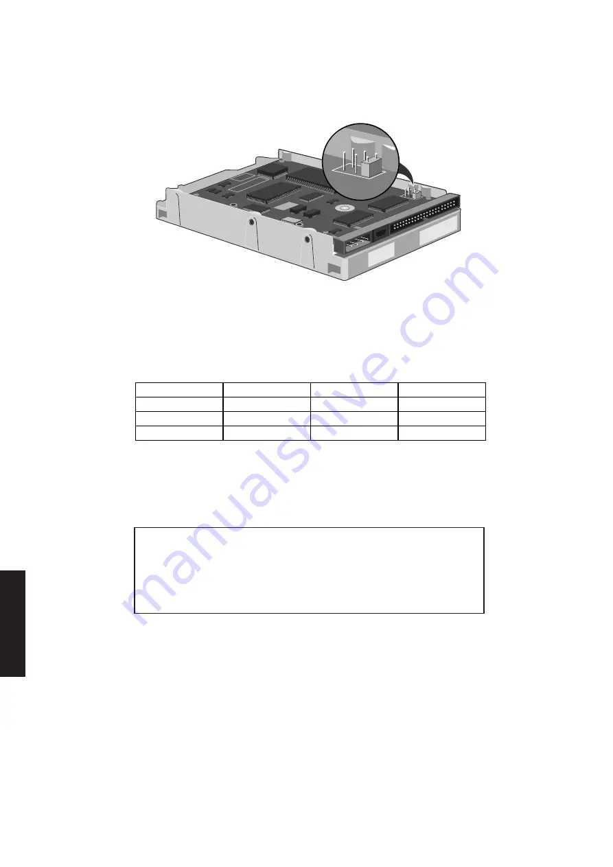
Three jumpers on the drive circuit are used to configure the drive. These are shown,
properly configured, in the following illustration.
The three jumpers are labelled DS (Drive select), CS (Cable select) and SP (Slave
present). The DS jumper must be fitted and the CS and SP jumpers not, in order for
the drive to function in an LS Pro.
Drive formats
The following table shows the physical format of the drives:
Drive
85
127
170
Disks
1
2
2
Heads
2
3
4
Tracks
3056
4584
6112
Formatting
These drives are low level formatted during manufacture. This format has been
optimized to allow the drive to provide maximum performance. Standard low level
formatting programs can only reduce the performance of the drive.
Warning
Do not attempt to perform a low level format on a ProDrive, this can only adversely affect
the performance of your drive. If you do try to format your drive most standard low level
formatting programs will return a “Drive formatted” message very quickly. In fact, the
drive has not been formatted.
Discache
The Quantum ProDrive ELS drives are fitted with 32kbytes of RAM and look-ahead
cache circuitry known as Discache.
When a read access is made to the drive, Discache loads subsequent data into the RAM.
If an attempt is made to read this data it is accessed from RAM rather than from the
disk, thus considerably reducing access times.
Cache performance benefits tend to be application dependent. Discache has a number
of alterable parameters which allow the cache to be configured for maximum
performance benefit in any given application.
Full information on configuring Discache is given in the Quantum specification.
Summary of Contents for Apricot LS Pro
Page 1: ...apricot HARDWARE TECHNICAL REFERENCE MITSUBISHI ELECTRIC LS Pro ...
Page 2: ...HARDWARE TECHNICAL REFERENCE ...
Page 6: ...CONTENTS ...
Page 9: ...Chapter 1 INTRODUCTION ...
Page 14: ...Chapter 2 SYSTEM UNIT ...
Page 37: ...Chapter 3 SYSTEM BOARD ...
Page 60: ...Chapter 4 PERIPHERAL ITEMS ...
Page 91: ...Chapter 5 MEMORY AND I O USAGE ...
Page 118: ...Appendix A SPECIFICATIONS ...
Page 125: ...Appendix B REVISION C SYSTEM BOARD ...
Page 130: ...ERROR BEEP CODES Appendix C ...
Page 134: ...INDEX ...


