Chapter 2
Chapter 6
Contents
Chapter 2
Chapter 5
System unit
Chapter 3
Chapter 2
LS PRO HARDWARE TECHNICAL REFERENCE 2/9
7. Replacement is the reverse of removal. However care must be taken to note the
following:
Warning
Remember to reconnect the power supply earth cable to the metalwork.
• The metalwork must be behind the switch operating lever of the power switch
linkage.
• A metal RFI screening tray is fitted in the base of the system unit. During the
replacement of the power supply metalwork the front edge of the tray can be
damaged.
In order to prevent damage occurring use a piece of card to hold down the
fingers at the front edge of the metalwork while the metalwork is replaced.
Once the metalwork is in place gently remove the card.
• Take care to ensure that the lugs on the bottom right of the metalwork are
properly engaged and that the metalwork does not foul on the fan.
The fan rests on a flexible foam pad which is compressed when the power
supply metalwork is in place. A slot is provided in the metalwork to allow a
small blunt instrument (flat bladed screwdriver) to push the fan down during
the replacement of the metalwork. Do not force the power supply metalwork
into position.
Removing the
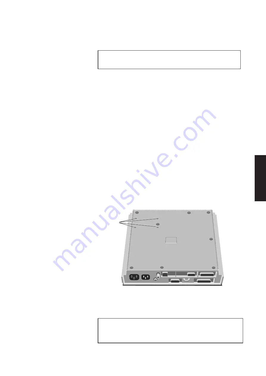
The hard disk drive is attached to the system unit base by four screws on the
hard disk drive
underside of the system unit. The following illustration identifies the screws which
hold the hard disk drive in place.
HARD DISK
DRIVE
SECURING
SCREWS
1. Remove the system unit top cover, system board metalwork and power supply
metalwork.
2. Disconnect the hard disk drive power and signal cables from the system board.
Warning
Do not attempt to disconnect the cables from the drive with the drive still in the system
unit. Attempting to do so will damage the drive circuit board.
Summary of Contents for Apricot LS Pro
Page 1: ...apricot HARDWARE TECHNICAL REFERENCE MITSUBISHI ELECTRIC LS Pro ...
Page 2: ...HARDWARE TECHNICAL REFERENCE ...
Page 6: ...CONTENTS ...
Page 9: ...Chapter 1 INTRODUCTION ...
Page 14: ...Chapter 2 SYSTEM UNIT ...
Page 37: ...Chapter 3 SYSTEM BOARD ...
Page 60: ...Chapter 4 PERIPHERAL ITEMS ...
Page 91: ...Chapter 5 MEMORY AND I O USAGE ...
Page 118: ...Appendix A SPECIFICATIONS ...
Page 125: ...Appendix B REVISION C SYSTEM BOARD ...
Page 130: ...ERROR BEEP CODES Appendix C ...
Page 134: ...INDEX ...


