Peripheral items
Chapter 4
Chapter 4
Chapter 6
Appendix A
Appendix C
Pr
eface
Chapter 4
4/18 LS PRO HARDWARE TECHNICAL REFERENCE
Interface
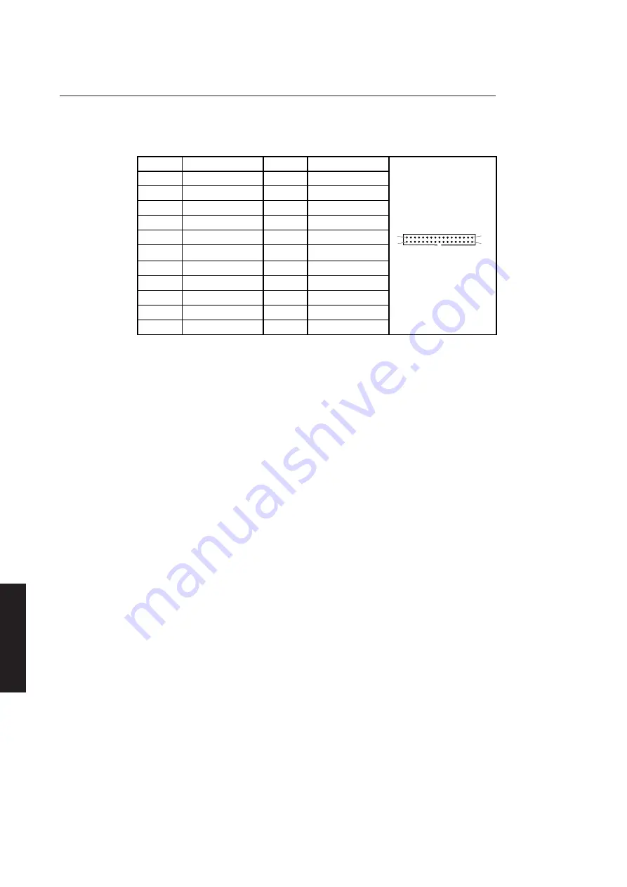
The drive has one connector. The pinout of the connector and an illustration are shown
below.
Connector
Pin
Function
Pin
Function
2
density select 1
14
drive select 2
3
not connected
16
motor on
4
not connected
18
direction
5
5V
20
step
6
density select 0
22
write data
7
5V
24
write enable
8
index
26
track 00
9
5V
28
write protect
10
drive select 0
30
read data
11
5V
32
head select
12
drive select 1
34
disk change
Note
All other pins are connected to 0 Volts.
Signal
Density select 0,1
descriptions
Not currently used.
Drive select 0,1,2
The drive select inputs are used to enable and disable the other input/output lines.
When a select input is low the drive is active and the input/output lines are enabled.
When a select input is high, all outputs from the drive are disabled and all inputs are
ignored.
Index
When the drive is selected this line is pulsed low for each revolution of the disk drive
spindle.
Motor on
When this input is taken low and a disk is inserted in the drive, the drive motor starts.
When this input is taken high or a disk is removed the drive motor stops.
Direction
If this input is high the step input causes the read/write head to step away from the
centre of the disk. If this input is low the head steps toward the centre of the disk.
Step
A low pulse on this input will cause the read/write head to move to the next track. The
direction of movement is determined by the direction input at the end of the step pulse.
2
1
34
33
Summary of Contents for Apricot LS Pro
Page 1: ...apricot HARDWARE TECHNICAL REFERENCE MITSUBISHI ELECTRIC LS Pro ...
Page 2: ...HARDWARE TECHNICAL REFERENCE ...
Page 6: ...CONTENTS ...
Page 9: ...Chapter 1 INTRODUCTION ...
Page 14: ...Chapter 2 SYSTEM UNIT ...
Page 37: ...Chapter 3 SYSTEM BOARD ...
Page 60: ...Chapter 4 PERIPHERAL ITEMS ...
Page 91: ...Chapter 5 MEMORY AND I O USAGE ...
Page 118: ...Appendix A SPECIFICATIONS ...
Page 125: ...Appendix B REVISION C SYSTEM BOARD ...
Page 130: ...ERROR BEEP CODES Appendix C ...
Page 134: ...INDEX ...


