Chapter 4
Chapter 6
Memory and I/O Usage
Appendix A
Appendix C
Pr
eface
Chapter 4Chapter 5
LS PRO HARDWARE TECHNICAL REFERENCE 5/19
Parallel control
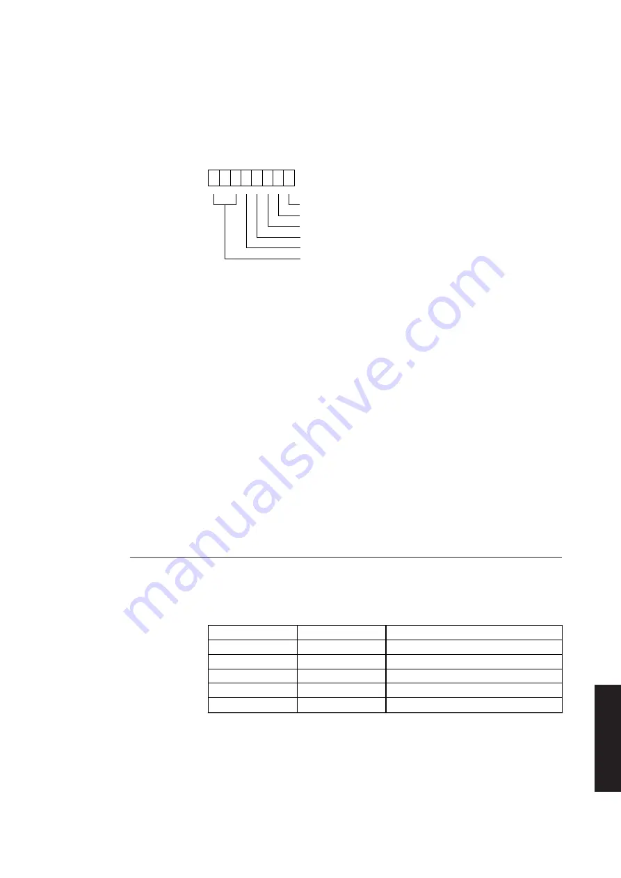
This parallel control port is a read or write port. A write operation to this port latches
port
the six least significant data bits of the bus. The sixth bit corresponds to the direction
control bit and is only applicable in extended mode. The significance of the bits is shown
below. A read operation to this port presents the system microprocessor with the data
that was last written to the port, with the exception of the write-only direction bit.
7 6 5 4 3 2 1 0
Pin 1 (STROBE)
Pin 14 (AUTO FD XT)
Pin 16 (INIT)
Pin 17 (SLCT IN)
IRQ EN
reserved
Bit 0
This bit controls the strobe signal to the printer. When this bit is set to
1 data is pulse-clocked into the printer
Bit 1
This bit controls the automatic feed XT (AUTO FEED XT) signal. When
this bit is set to 1, the printer will automatically line feed after each line
is printed.
Bit 2
This bit controls the initialize printer (INIT) signal. When this bit is set
to 0, the printer is selected.
Bit 3
This bit controls the select in (SLCT IN) signal. When this bit is set to
1, the printer is selected.
Bit 4
This bit enables the parallel port interrupt. When this bit is set to 1 an
interrupt occurs when the acknowledge signal changes from active to
inactive.
Bits 5-7
Reserved
Video DAC
The video digital to analogue converter (DAC) is enabled in the video controller and
contains a colour lookup table and three DACs. Four I/O ports are used to access the
Video DAC.
Port
Read/Write
Function
03C6
R/W
Pixel Mask
03C7
R
DAC state register
03C7
W
Pixel address (read mode)
03C8
R/W
Pixel address (write mode)
03C9
R/W
Pixel data register
These registers comply with the VGA standard. They are described in detail in the
manufacturers data sheet.
Summary of Contents for Apricot LS Pro
Page 1: ...apricot HARDWARE TECHNICAL REFERENCE MITSUBISHI ELECTRIC LS Pro ...
Page 2: ...HARDWARE TECHNICAL REFERENCE ...
Page 6: ...CONTENTS ...
Page 9: ...Chapter 1 INTRODUCTION ...
Page 14: ...Chapter 2 SYSTEM UNIT ...
Page 37: ...Chapter 3 SYSTEM BOARD ...
Page 60: ...Chapter 4 PERIPHERAL ITEMS ...
Page 91: ...Chapter 5 MEMORY AND I O USAGE ...
Page 118: ...Appendix A SPECIFICATIONS ...
Page 125: ...Appendix B REVISION C SYSTEM BOARD ...
Page 130: ...ERROR BEEP CODES Appendix C ...
Page 134: ...INDEX ...


