Chapter 2
Chapter 6
Contents
Chapter 2
Chapter 5
System unit
Chapter 3
Chapter 2
LS PRO HARDWARE TECHNICAL REFERENCE 2/15
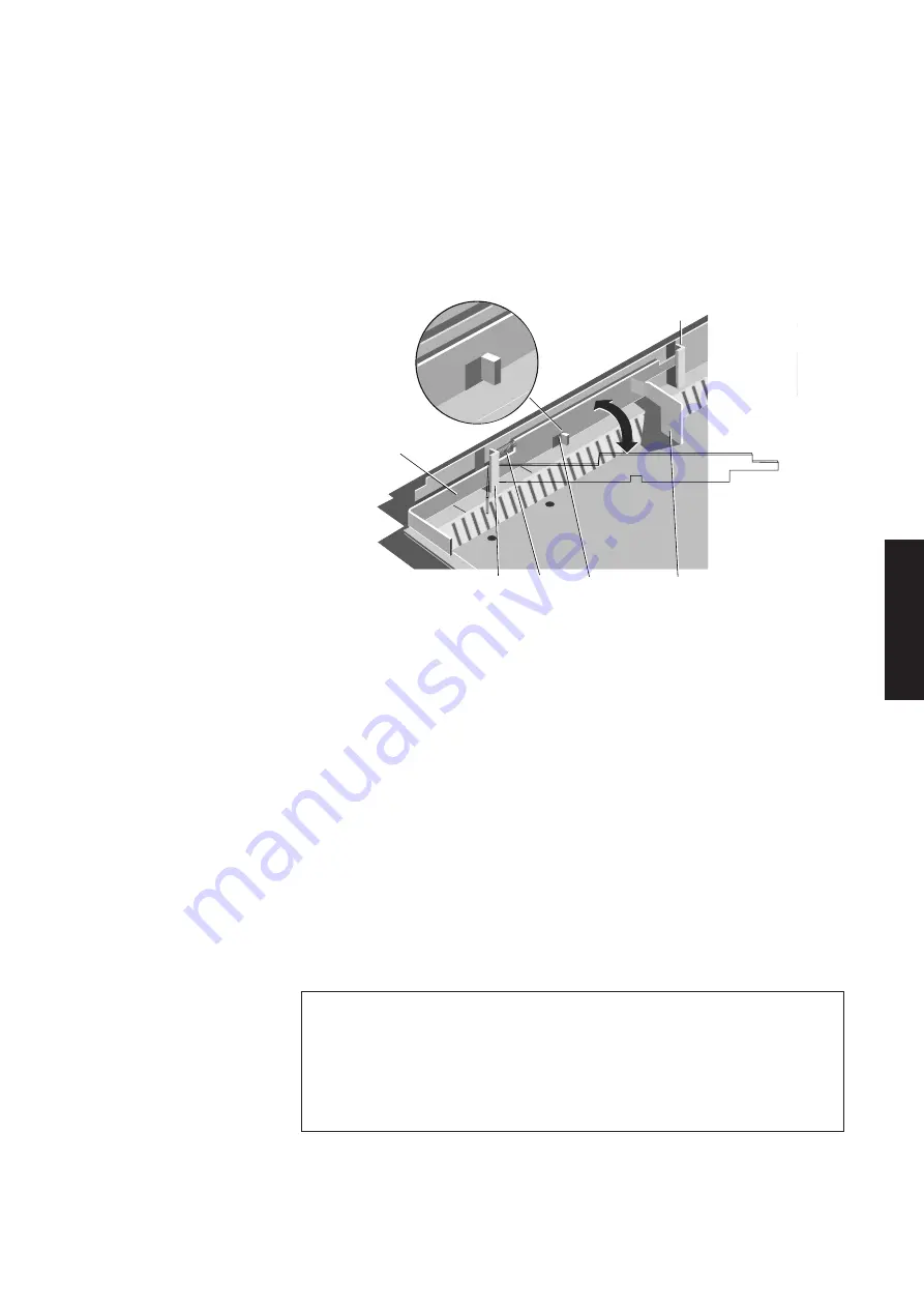
2. Using a pair of thin nosed pliers, disconnect the spring and put it somewhere safe.
3. Exerting gentle inward pressure on the operating lever, slide the power switch
linkage forward past the rear of the two ribs, far enough to free the back of the
linkage from the rear slot.
4. Slide the linkage back bending it gently to allow it to pass to the right of the rear
slot and push it as far back as it will travel.
OPERATING
LEVER
RIB
FRONT
SLOT
SPRING
REAR
SLOT
POWER SWITCH
LINKAGE
INWARD
OUTWARD
5. With the 90
°
bend at the front of the linkage against the front of the two slots
swing the rear of the linkage into the centre of the system unit.
Note
There should be no resistance to this movement. If there is resistance you have not
pushed the linkage far enough back.
6. Slide the linkage back through the slot and lift it clear.
7. Replacement is simply the reverse of removal except that gentle inward pressure
must be exerted to the front of the linkage to allow it to pass the front rib. Do
not force the linkage into place.
RFI screening tray
The LS Pro system unit base is fitted with a metal RFI screening tray and a plastic
and insulation
insulation sheet during manufacture. The metal tray reduces RFI emissions from the
sheet
system unit and ensures compliance with international regulations.
The plastic sheet insulates components inside the system unit from the RFI
tray. Both components are essential.
There should never be any need to remove the tray or the screening sheet.
However if you do need to remove them you must ensure that they are
replaced correctly when you reassemble the system.
Summary of Contents for Apricot LS Pro
Page 1: ...apricot HARDWARE TECHNICAL REFERENCE MITSUBISHI ELECTRIC LS Pro ...
Page 2: ...HARDWARE TECHNICAL REFERENCE ...
Page 6: ...CONTENTS ...
Page 9: ...Chapter 1 INTRODUCTION ...
Page 14: ...Chapter 2 SYSTEM UNIT ...
Page 37: ...Chapter 3 SYSTEM BOARD ...
Page 60: ...Chapter 4 PERIPHERAL ITEMS ...
Page 91: ...Chapter 5 MEMORY AND I O USAGE ...
Page 118: ...Appendix A SPECIFICATIONS ...
Page 125: ...Appendix B REVISION C SYSTEM BOARD ...
Page 130: ...ERROR BEEP CODES Appendix C ...
Page 134: ...INDEX ...


