Memory and I/O Usage
Chapter 4
Chapter 6
Appendix A
Appendix C
Pr
eface
Chapter 4Chapter 5
5/6 LS PRO HARDWARE TECHNICAL REFERENCE
Interrupt controllers
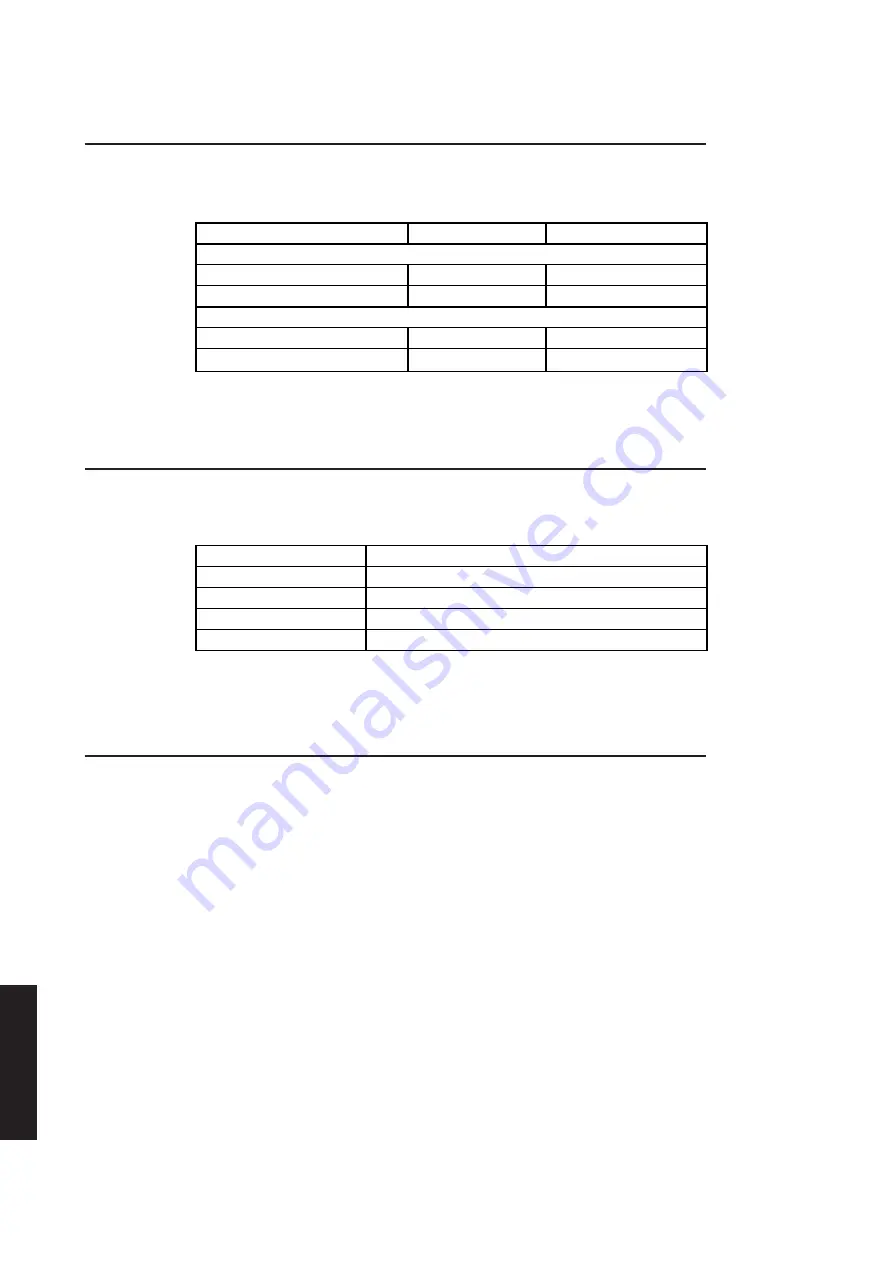
The interrupt controllers are programmed by writing to four 8-bit I/O ports. These are
listed in the following table.
Address
R/W
Function
Master controller
0020h
R/W
Port 1
0021h
R/W
Port 2
Slave controller
00A0h
R/W
Port 1
00A1h
R/W
Port 2
Full details on programming 8259 interrupt controllers are given in the manufacturers
data sheet.
System timers
The 8254 compatible system timer is accessed at I/O locations 0040h-0043h. The
following table identifies the function of each port.
Address
Function
0040h
Counter 0 count
0041h
Counter 1 count
0042h
Counter 2 count
0043h
Control register
A full description of programming 8254 timers is included in the manufacturers
specification and is not repeated here.
Keyboard controller
The 8042 keyboard controller has two ports which are in I/O space at locations 0060h
and 0064h. The port at 0060h is an output port where keyboard data is made available
to the system. The port at 0064h is the command/status port which is described in
more detail below.
Command/status
When the system reads I/O location 0064h it receives information about the status of
port
the controller. When the system writes to I/O location 0064h the byte is interpreted
as a command.
Summary of Contents for Apricot LS Pro
Page 1: ...apricot HARDWARE TECHNICAL REFERENCE MITSUBISHI ELECTRIC LS Pro ...
Page 2: ...HARDWARE TECHNICAL REFERENCE ...
Page 6: ...CONTENTS ...
Page 9: ...Chapter 1 INTRODUCTION ...
Page 14: ...Chapter 2 SYSTEM UNIT ...
Page 37: ...Chapter 3 SYSTEM BOARD ...
Page 60: ...Chapter 4 PERIPHERAL ITEMS ...
Page 91: ...Chapter 5 MEMORY AND I O USAGE ...
Page 118: ...Appendix A SPECIFICATIONS ...
Page 125: ...Appendix B REVISION C SYSTEM BOARD ...
Page 130: ...ERROR BEEP CODES Appendix C ...
Page 134: ...INDEX ...


