Chapter 4
Revision C system board
Appendix A
Appendix C
Pr
eface
LS PRO HARDWARE TECHNICAL REFERENCE B/3
Chapter 6Chapter 4Appendix B
Extension
The CL-GD5410 video controller has a number of Extension registers. By default these
registers
registers are accessed using the Graphics Controller index and data registers.
The extension registers are listed in tables which follow. A full description of the
registers is included in the manufacturers data sheet and is not reproduced here.
Design revision
AA
Reserved
AC-AD
Alternate extension decode high
AE
Alternate extension decode low
AF
Reserved
B0-B9
Scratch register 5-0
BA-BF
Attribute and graphics control
C0
Cursor attributes
C1
Graphics controller memory latches 0-3
C2-C5
Reserved
C6-C7
RAMDAC controls
C8
Graphics and attribute test
C9
Reserved
CA-DF
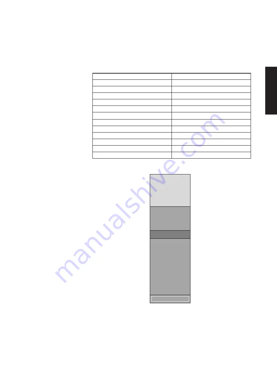
Memory map
100000
F0000
E4000
E0000
C4000
C0000
BIOS and
5410 BIOS
GRAPHICAL BOOT
SETUP and
SECURITY
82596 RPL
BUS
MEMORY
NOTE 1
1M
960K
896K
784K
768K
912K
1. This area is occupied by the ROM in the option ROM socket if it is fitted.
The 5410 BIOS is integrated with the system BIOS in the F0000h to FFFFFh region.
All the code in the region E0000h to EFFFFh region is used only at boot. Thus with
the option ROM socket empty the region from C0000h to EFFFFh is available as DOS
UMB space.
Summary of Contents for Apricot LS Pro
Page 1: ...apricot HARDWARE TECHNICAL REFERENCE MITSUBISHI ELECTRIC LS Pro ...
Page 2: ...HARDWARE TECHNICAL REFERENCE ...
Page 6: ...CONTENTS ...
Page 9: ...Chapter 1 INTRODUCTION ...
Page 14: ...Chapter 2 SYSTEM UNIT ...
Page 37: ...Chapter 3 SYSTEM BOARD ...
Page 60: ...Chapter 4 PERIPHERAL ITEMS ...
Page 91: ...Chapter 5 MEMORY AND I O USAGE ...
Page 118: ...Appendix A SPECIFICATIONS ...
Page 125: ...Appendix B REVISION C SYSTEM BOARD ...
Page 130: ...ERROR BEEP CODES Appendix C ...
Page 134: ...INDEX ...


