System unit
Contents
Chapter 2
Chapter 5
Chapter 6
Chapter 3
Chapter 2
2/8 LS PRO HARDWARE TECHNICAL REFERENCE
Chapter 2
1. Remove the system board metalwork.
2. Remove the four screws which secure the floppy drive and remove the drive.
3. Replacing the floppy drive is simply the reversal of removal. If the drive being
installed is a replacement ensure that the drive select switch on the side of the
drive is in the same position as that on the old drive.
Removing the
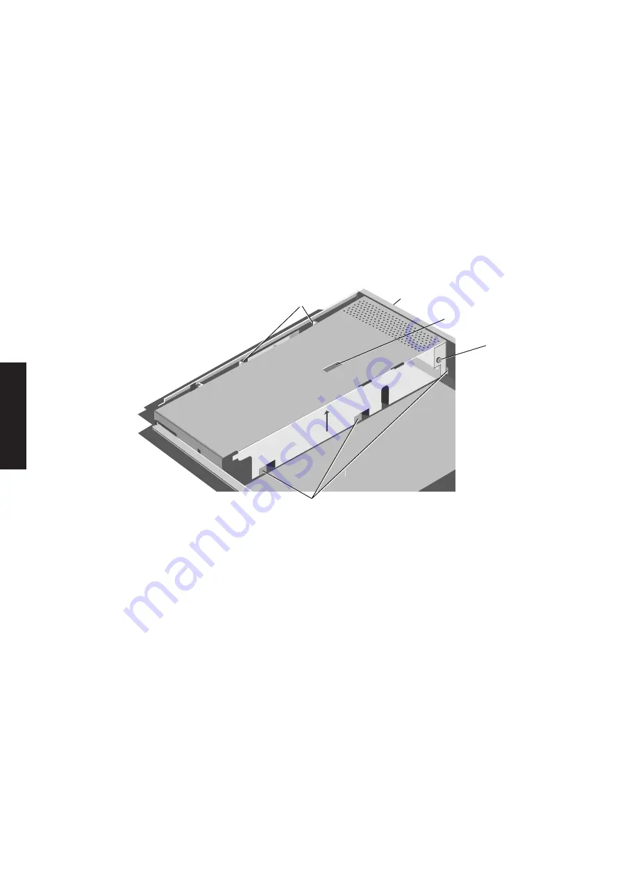
The power supply metalwork covers the top of the power supply and divides the
power supply
system unit, it applies gentle pressure to the top of the system unit fan. The system
metalwork
board metalwork uses the power supply metalwork for location.
The power supply metalwork is secured by two screws and a number of lugs.
SECURING
LUGS
SECURING
SCREW
SECURING
LUGS
EARTH
BOND
SCREW
FAN LOCATION
SLOT
1. Remove the system board metalwork.
2. Remove the earth bond screw which secures the system board escutcheon plate
to the power supply metalwork.
3. Remove the screw in the rear panel between the mains inlet and outlet which
secures the power supply metalwork.
4. Slide the power supply metalwork forward by approximately 6mm to free the
lugs.
5. An earth cable connects the power supply to the metalwork. Gently lift the
metalwork and carefully turn it over.
6. Remove the screw which secures the cable to the metalwork and lift the
metalwork clear.
Summary of Contents for Apricot LS Pro
Page 1: ...apricot HARDWARE TECHNICAL REFERENCE MITSUBISHI ELECTRIC LS Pro ...
Page 2: ...HARDWARE TECHNICAL REFERENCE ...
Page 6: ...CONTENTS ...
Page 9: ...Chapter 1 INTRODUCTION ...
Page 14: ...Chapter 2 SYSTEM UNIT ...
Page 37: ...Chapter 3 SYSTEM BOARD ...
Page 60: ...Chapter 4 PERIPHERAL ITEMS ...
Page 91: ...Chapter 5 MEMORY AND I O USAGE ...
Page 118: ...Appendix A SPECIFICATIONS ...
Page 125: ...Appendix B REVISION C SYSTEM BOARD ...
Page 130: ...ERROR BEEP CODES Appendix C ...
Page 134: ...INDEX ...


