Peripheral items
Chapter 4
Chapter 4
Chapter 6
Appendix A
Appendix C
Pr
eface
Chapter 4
4/2 LS PRO HARDWARE TECHNICAL REFERENCE
4.1
POWER SUPPLY
Description
The power supply is an extremely compact unit which fits inside the system unit and
provides DC power for the system unit and an AC outlet to power a monitor. The unit
contains: mains inlet and outlet, voltage selection jumper, DC power outlet for the
system board and power outlet for the system unit fan.
The power supply is designed to meet international safety standards.
Mains input to the power supply is at the rear of the PSU via a 3-pin AC inlet. Alongside
the input connector is an auxiliary 3-pin outlet which supplies power to a monitor. A
single low voltage output cable harness supplies power within the system unit. A two
pin connector on the power supply PCB provides power for the system unit fan.
Warning
The auxiliary AC outlet must only be used to power monitors approved by Apricot.
The power supply on/off switch acts as the system on/off switch and is operated from
the front panel via a mechanical linkage.
The unit generates an active high Power good signal which is only taken high after the
DC outputs are stabilised. The signal goes low at least 1mS before the DC outputs fall
outside specification. This signal is used to disable read and write operations to the
RTC, battery backed RAM and the Security RAM before power is removed.
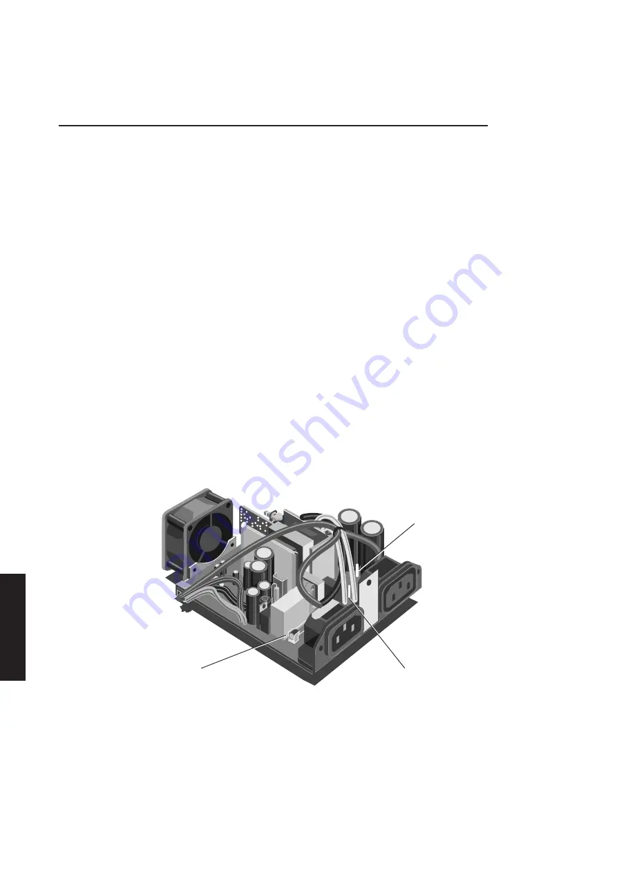
The power supply unit is shown in the following illustration.
220-240V JUMPER
110V-120V JUMPER
FUSE
The unit can accept power from either 110-120V or 220-240V AC supplies. The input
voltage is selected by a jumper on the power supply PCB. The location of the jumper
is shown in the illustration above.
An internal 4A 250V (T4H) fuse is fitted in the power supply. In the event of a failure
only replace the fuse with one of the same type and rating. Determine the cause of the
failure before replacing the fuse.
Summary of Contents for Apricot LS Pro
Page 1: ...apricot HARDWARE TECHNICAL REFERENCE MITSUBISHI ELECTRIC LS Pro ...
Page 2: ...HARDWARE TECHNICAL REFERENCE ...
Page 6: ...CONTENTS ...
Page 9: ...Chapter 1 INTRODUCTION ...
Page 14: ...Chapter 2 SYSTEM UNIT ...
Page 37: ...Chapter 3 SYSTEM BOARD ...
Page 60: ...Chapter 4 PERIPHERAL ITEMS ...
Page 91: ...Chapter 5 MEMORY AND I O USAGE ...
Page 118: ...Appendix A SPECIFICATIONS ...
Page 125: ...Appendix B REVISION C SYSTEM BOARD ...
Page 130: ...ERROR BEEP CODES Appendix C ...
Page 134: ...INDEX ...


