Chapter 2
Chapter 6
Contents
Chapter 2
Chapter 5
System unit
Chapter 3
Chapter 2
LS PRO HARDWARE TECHNICAL REFERENCE 2/11
Removing the
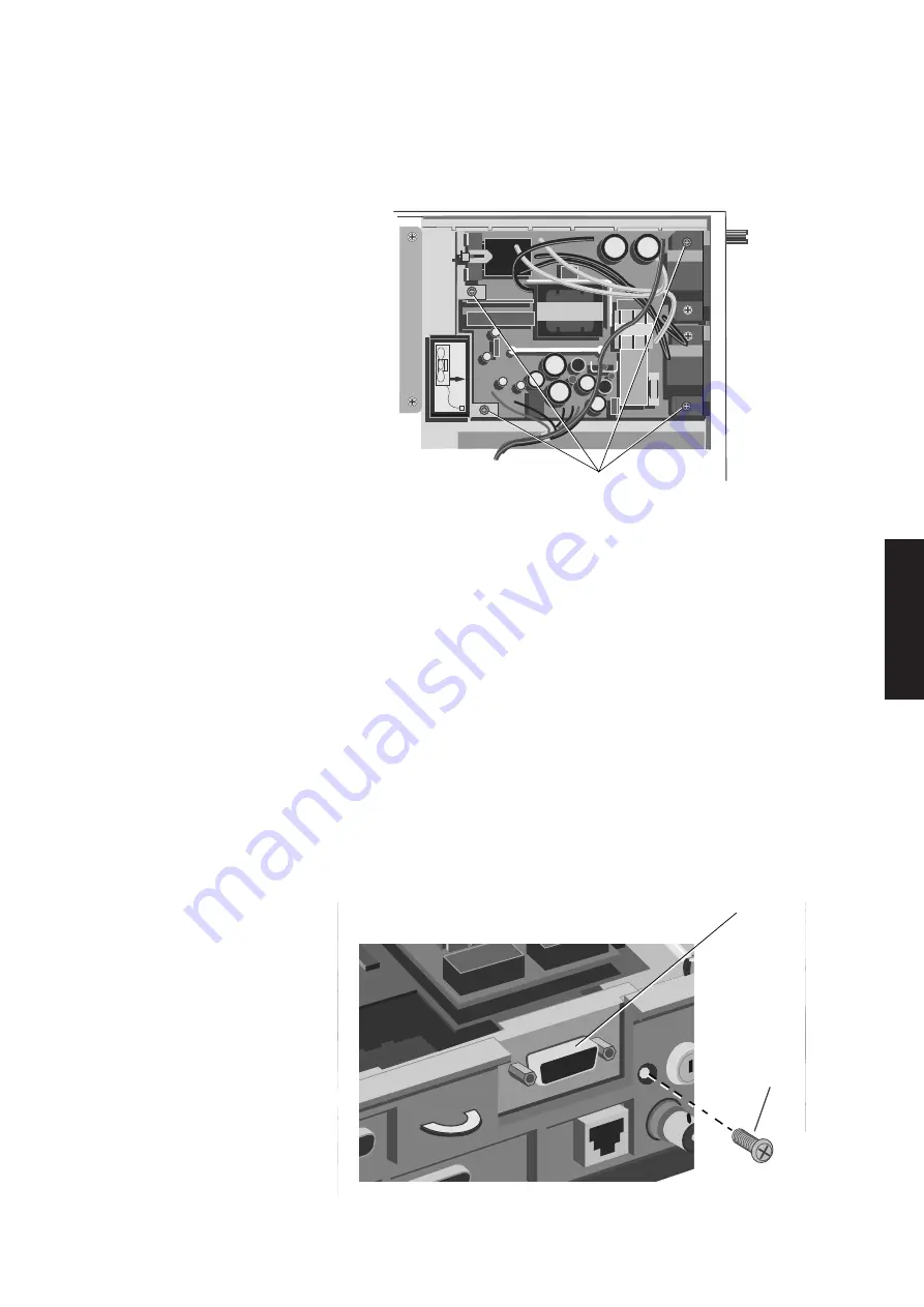
The power supply is secured to the bottom of the system unit by four screws. The
power supply
following illustration identifies the screws that must be removed and the connectors
that must be disconnected in order to remove the power supply.
SECURING
SCREWS
1. Remove the power supply metalwork.
2. Disconnect the system board and fan power connectors.
3. Lift out the fan.
4. Remove the four screws securing the power supply.
5. Lift the power supply clear of the system unit.
6. Replacement is simply the reverse of removal. Ensure that the voltage range
selection jumper is in the correct position for the mains supply available. The
jumper is identified in section 4 of this manual.
Removing a
The Token-Ring module is secured to three standoff pillars inside the system unit,
Token-Ring
and to the escutcheon plate at the rear of the system unit. To remove the module
module
follow the instructions below:
1. Remove the system board metalwork.
2. Remove the screw in the rear panel of the system unit, to the right of the Token-
Ring connector.
SECURING
SCREW
TOKEN RING
CONNECTOR
Summary of Contents for Apricot LS Pro
Page 1: ...apricot HARDWARE TECHNICAL REFERENCE MITSUBISHI ELECTRIC LS Pro ...
Page 2: ...HARDWARE TECHNICAL REFERENCE ...
Page 6: ...CONTENTS ...
Page 9: ...Chapter 1 INTRODUCTION ...
Page 14: ...Chapter 2 SYSTEM UNIT ...
Page 37: ...Chapter 3 SYSTEM BOARD ...
Page 60: ...Chapter 4 PERIPHERAL ITEMS ...
Page 91: ...Chapter 5 MEMORY AND I O USAGE ...
Page 118: ...Appendix A SPECIFICATIONS ...
Page 125: ...Appendix B REVISION C SYSTEM BOARD ...
Page 130: ...ERROR BEEP CODES Appendix C ...
Page 134: ...INDEX ...


