System unit
Contents
Chapter 2
Chapter 2
Chapter 5
Chapter 6
Chapter 3
Chapter 2
2/20 LS PRO HARDWARE TECHNICAL REFERENCE
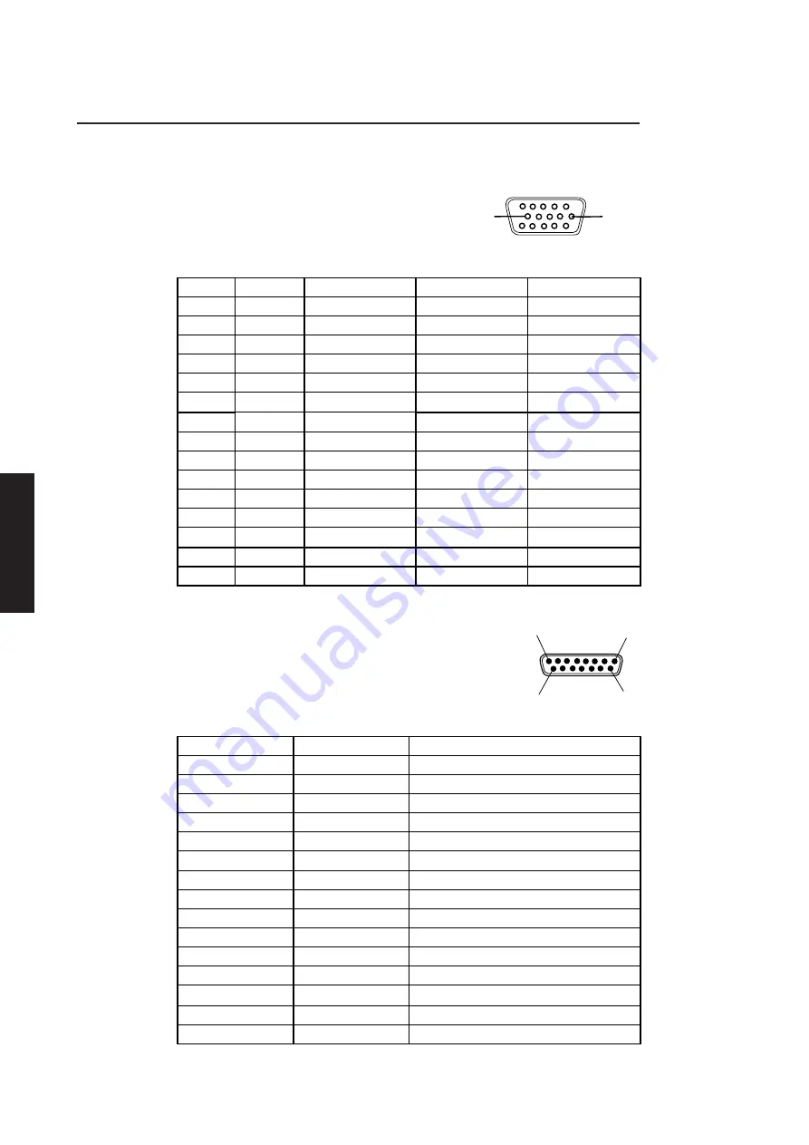
System unit connectors
The following illustrations and tables show the layout, pin numbering and pinout of each
of the connectors on the rear panel of the system unit.
VGA
The VGA display connector is a 15-pin D-shell.
1
5
10
6
11
15
Pin
I/O
Output
Mono
Colour
1
O
Red
No pin
Red
2
O
Green
Mono
Green
3
O
Blue
No pin
Blue
4
NA
Reserved
No pin
No pin
5
NA
Digital Gnd
Self Test
Self Test
6
NA
Red rtn
Key pin
Red rtn
7
NA
Green rtn
Mono rtn
Green rtn
8
NA
Blue rtn
No pin
Blue rtn
9
NA
Plug
No pin
No pin
10
NA
Digital Gnd
Digital Gnd
Digital Gnd
11
NA
Reserved
No pin
Digital Gnd
12
NA
Reserved
Digital Gnd
No pin
13
O
Hsync
Hsync
Hsync
14
O
Vsync
Vsync
Vsync
15
NA
Reserved
No pin
No pin
Ethernet
Thick
The thick Ethernet connector is a 15-pin female D-shell
1
8
9
15
which uses a slide to hold the male and female connectors
together.
Pin
I/O
Signal
1
NA
Collision presence shield
2
I
Collision presence (+ve)
3
O
Transmit (+ve)
4
NA
Receive shield
5
I
Receive (+ve)
6
NA
Power return
7
NA
Reserved (+ve)
8
NA
Reserved shield
9
I
Collision presence (-ve)
10
O
Transmit (-ve)
11
NA
Transmit shield
12
I
Receive (-ve)
13
NA
Power
14
NA
Power shield
15
NA
Reserved (-ve)
Summary of Contents for Apricot LS Pro
Page 1: ...apricot HARDWARE TECHNICAL REFERENCE MITSUBISHI ELECTRIC LS Pro ...
Page 2: ...HARDWARE TECHNICAL REFERENCE ...
Page 6: ...CONTENTS ...
Page 9: ...Chapter 1 INTRODUCTION ...
Page 14: ...Chapter 2 SYSTEM UNIT ...
Page 37: ...Chapter 3 SYSTEM BOARD ...
Page 60: ...Chapter 4 PERIPHERAL ITEMS ...
Page 91: ...Chapter 5 MEMORY AND I O USAGE ...
Page 118: ...Appendix A SPECIFICATIONS ...
Page 125: ...Appendix B REVISION C SYSTEM BOARD ...
Page 130: ...ERROR BEEP CODES Appendix C ...
Page 134: ...INDEX ...


