background image


      Global leader in wind measurement technology 

110 Riggs Road 

· 

Hinesburg 

· 

VT 05461 USA 

  ·  

TEL (802) 482-2255  

· 

 FAX (802) 482-2272   

·  

EMAIL 

[email protected]


NRG_34m_TallTower_Installation_Manual_and_Specifications_Rev_1.05.docx   


19 April 2011 


NRG 34 m 

TallTower™ 

Installation Manual & Specifications 


Summary of Contents for TallTower 34 m

Page 1: ...logy 110 Riggs Road Hinesburg VT 05461 USA TEL 802 482 2255 FAX 802 482 2272 EMAIL sales nrgsystems com NRG_34m_TallTower_Installation_Manual_and_Specifications_Rev_1 05 docx 19 April 2011 NRG 34 m TallTower Installation Manual Specifications ...

Page 2: ...2 NRG_34m_TallTower_Installation_Manual_and_Specifications_Rev_1 05 docx 19 April 2011 Specifications are subject to change without notice ...

Page 3: ...s may pose a threat to low flying crop dusting aircraft Notify appropriate parties and install warning devices as needed We assume no responsibility or liability in connection with any act error omission or for any injury loss accident delay inconvenience irregularity or damage related to any TallTower installation DANGER YOU CAN BE KILLED IF THIS TOWER COMES NEAR ELECTRIC POWER LINES or IF YOU IN...

Page 4: ...hors 14 Tip Cellular Coverage 14 Site Layout Map 14 Tower Assembly 16 Assemble the Baseplate 16 Install the Anchors 19 Tube Layout 19 SI Units 19 Imperial Units 19 Install the Base Tube 20 Attach sensors and booms 21 Spiral wrap your sensor cables 21 Attach the Guy Wires 22 Organize and layout the lifters and guy wires 22 Shackle guy wires to the guy rings 22 Roll out each guy wire from the tower ...

Page 5: ...Tower Layout 40 Site Layout 41 Baseplate Geometry 43 Appendix B Anchoring Guidelines 45 Determine site soil and anchor type before you order your tower 45 Anchor Choices and other considerations 45 Screw In Anchor description 45 Arrowhead Anchor description 47 Rock Anchor description 48 Concrete Anchor description 48 Installing Screw In Anchors 49 Installing Arrowhead Anchors 49 Installing Rock An...

Page 6: ...amiliar with all tower parts and terminology If you are NOT familiar with erecting towers of this type seek professional guidance We will gladly help answer any questions If you have never installed a TallTower before seek the assistance of a qualified installer If you are not thoroughly familiar with all components of the tower including all hardware and how all components function DO NOT attempt...

Page 7: ...wer during an electrical storm DO NOT erect tower within 1 times the tower height of walkways roads or buildings DO NOT permit unauthorized personnel onto the site while the tower is being installed DO NOT raise or lower the tower on a day with high winds or gusty winds DO NOT use mechanical tensioning devices to adjust guy wires DO NOT use rebar anchors DO NOT stand in line with directly in front...

Page 8: ...ole is included with the purchase of this tower are also required to raise the tower The ginpole for the 34m TallTower is NOT compatible with other NRG TallTowers The ginpoles from other NRG TallTowers are not compatible with the 34 m tower Please see the Glossary for pictures and descriptions of tower parts hardware and accessories Experience Required If you have no prior experience with TallTowe...

Page 9: ...etic base to straighten the tower Compass for aligning direction sensors Permanent marker for labeling lower ends of cables 2 12 V deep cycle marine battery for electric winch Hankmaster 5000 guy wire tool optional Gloves 2 way radios or walkie talkies Electric drill with 5 16 inch bit for unpacking and attaching top tube Band cutters for unpacking 2 5 m 8 feet stepladder for reaching end of ginpo...

Page 10: ......

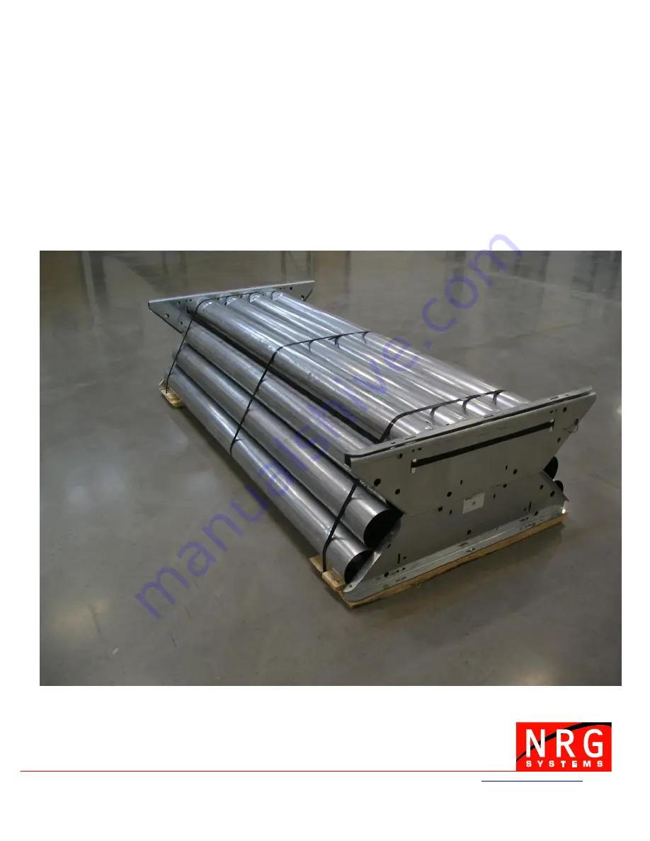
Page 11: ...urchased this tower as part of an NRG NOW System the electronics sensors and associated accessories are packaged separately It is very important that you understand how to unpack the contents of the packaging safely The recommended sequence to unpack the tower is described in this section of the manual The tubes may shift position suddenly when bands are cut so please read this section carefully t...

Page 12: ...en placed into a truck with one end against the front wall of the truck s cargo area and no forklift available to remove it from the truck In this case you will be able to follow instructions in this section of the manual to unpack the contents and unload from the truck by hand Note You will NOT be able to unpack the contents if the tower package has been loaded into a truck sideways If it has bee...

Page 13: ... only remove one end plate assembly that is OK Remove the end plate and set aside The tube contents will now be exposed Beginning at the top remove the contents of the tubes These contents will include screw in anchors coils of cable ground rods guy rings rocker plates and the hardware kits At this point there should only be 152 mm 6 inch diameter tubes remaining on the pallet With the band cutter...

Page 14: ...your specific site Depending on the soil type anchoring can take varying levels of planning effort and time Be sure to know what soil types you are dealing with as part of your pre installation planning process Note 5 6 inch diameter screw anchors are included with the tower Other anchor types must be ordered separately Please refer to the anchoring guidelines in Appendix B of this manual for more...

Page 15: ... off the line Do not move them more than 1 m 3 feet off the line although some sites may require a compromise because anchors may not be able to be located at the preferred spot NOTE Extra care will have to be taken while raising the tower if anchor placement is not perpendicular to the tower as it lays on the ground anchors are not at the same elevation side anchors and base plate are not in a st...

Page 16: ...late in this location Assemble 4 of the 6 large triangular baseplate sections as shown below inserting 8 5 16 x 3 4 carriage bolts in holes closest to the center of each triangular baseplate section Leave nuts somewhat loose tighten by hand only Flip over the baseplate assembly and prop up on one edge with a block of wood to allow access to underside of baseplate Attach vertical pieces to the cent...

Page 17: ... in the baseplate At the beginning of a lift particularly for the gin pole the winch forces are largely horizontal These forces tend to slide the baseplate toward the winch and or tip the baseplate up on edge To counteract these forces it is highly recommended that the baseplate be anchored against sliding and tipping There are several possible techniques depending on the terrain soil and subseque...

Page 18: ...inch Rock anchors to the baseplate On rock or shallow soils attach rock anchors to the baseplate particularly along the front edge These should be positioned and attached to hold the edge of the baseplate down as well as keep it from sliding Cable to the Guy Anchor A cable made up as a bridle connected to the tower bolt can be run to the inner anchor opposite the winch or to an anchor nearer the b...

Page 19: ...over the last tube listed in each section Section 1 Section 2 Section 3 Section 4 Base Tube 4 2 2 m 152 mm dia tubes Lifters attached to this guy ring are color coded Red 4 2 2 m 152 mm dia tubes Lifters attached to this guy ring are color coded White 4 2 2 m 152 mm dia Lifters attached to this guy ring are color coded Black 4 2 2 m 152 mm dia tubes Lifters attached to this guy ring are color code...

Page 20: ...o the outer tube s flare The inner tube will be stopped Aligning the weld seams visible in interior of tube of each tower section will make it easier to slide the sections together Continue to assemble the tubes and place guy rings over the tubes according to the sequence above Make sure the guy ring is placed so the guy ring corners are bent towards the baseplate and the guy ring corners are in l...

Page 21: ...vel direction vane 2 34 m level anemometers and 1 20 m level anemometer It is always easiest to run the cables from the sensor and booms down the tower Refer to Appendix E for wind vane alignment tips Spiral wrap your sensor cables Spiral wrap sensor cables around the tower one wrap per tube joint The spiral promotes vortex shedding and reduces natural frequency oscillations of the tower Use elect...

Page 22: ...res the guy wires opposite the winch are attached to their guy rings rolled out and secured to their anchors first followed by the side guy wires to eliminate crossing Shackle guy wires to the guy rings Secure the back guy wires first to their corresponding guy rings using the shackles Attach the guy wires to the guy ring holes under the tower tube Roll out the back guy wires to their anchor point...

Page 23: ...ecifications_Rev_1 05 docx 19 April 2011 CORRECT Do not un spool cable off the side of the coil as shown below NO The Hankmaster can be used to roll the guy wires out to the anchors See Appendix F for instructions for building and using a Hankmaster ...

Page 24: ...coming from the tower and the U bolt part clamps down on the dead end of the guy wire Never saddle a dead horse may help you to remember how to secure the wire rope clips Leave a little slack in the guy wire and tighten the wire rope clip nuts Don t tighten the wire rope clip nuts too tightly you will need to adjust the guy length numerous times as the tower is erected Shackle lifter wires to the ...

Page 25: ...he holes in the ginpole base tube with the holes in the baseplate s vertical channels and insert the x 8 bolt through the baseplate holes and the eye in the safety cable Secure the bolt with the provided nut Slide together the 4 tubes that comprise the ginpole Slide sections together until a hard stop is reached and thread the safety cable through each tube as it is assembled Aligning the weld sea...

Page 26: ...ates to the top section of the ginpole with the large bolt 3 4 inch x 8 inches making sure that the bolt goes through the eye of the ginpole safety cable Also place the 2 supplied graded 5 16 x 3 4 bolts at the ends of the rocker plates Attach the 2 quick links to the holes on the bottom side towards tower of the rocker plate Ginpole safety cable ...

Page 27: ... 45 7 m length of 12 mm 1 2 inch diameter brown polypropylene rope Cut the rope in half to make two 22 m 75 ft pieces Tie one piece from each side anchor to the top of the ginpole to stabilize the ginpole while it is being raised Warning Failure to use the ginpole ropes could cause the ginpole to fall over to either side during the lift Be sure to tie the safety ropes securely to the side anchors ...

Page 28: ...ower 3 Black 2 2 White 1 1 Red 1 bottom toward base of tower Table 4 Configure the helper ginpole Put the helper ginpole standing vertically pulleys pointing towards the sky on the baseplate behind the main ginpole Line up the holes in the helper ginpole with the holes in the baseplate s vertical channels Slide the x 8 bolts through holes to secure in a vertical position Secure the bolts with the ...

Page 29: ...29 NRG_34m_TallTower_Installation_Manual_and_Specifications_Rev_1 05 docx 19 April 2011 ...

Page 30: ...own ropes are both snug If the ginpole is off center carefully adjust the ropes to re center As the ginpole comes up remove the helper ginpole when the winch cable is no longer in contact with the pulleys on the end of the helper ginpole Pay attention to the lifters to make sure they are not caught on objects in the area stumps debris rocks equipment etc Also check that they are not crossed over e...

Page 31: ... proper tension be maintained on side guy wires at all times during the lifting procedure to provide side support for the tower Too little tension can allow the tower to buckle to the side Too much tension may cause failure of the tower anchors or guy wires There must always be visible slack in the guy wires If no slack is visible the tension is too great Once the tower is vertical two people of a...

Page 32: ...ns_Rev_1 05 docx 19 April 2011 2 Now loosen the lower clips loosening the lowest clip slowly allowing the loop to slide which will slacken the guy wire 3 Retighten the lowest wire rope clip 4 Repeat as necessary from step 1 to create the proper cable tension ...

Page 33: ...hown below Then 1 Loosen the lower 2 wire rope clips as shown below 2 Pull the 2 cables apart to form a loop similar to the loop made while loosening then tighten the lowest rope clip to trap the loop between the upper and lower rope clips as shown below 3 Loosen the upper rope clip and pull the tail to remove the loop 4 Finally tighten the upper clip 5 Repeat as necessary from step 1 to tighten t...

Page 34: ... this ONLY when the winch is stopped Readjust with wire rope clips letting cable out or pulling loose cable in see inchworm technique Work slowly and smoothly Fast uneven movements tend to make the tower bounce shake or swing Be sure that communication between all members of the lifting team is clear and concise Continue lifting and adjusting until the tower is about 60 degrees above horizontal ju...

Page 35: ... back guy wires to allow the tower to straighten Transfer the lifters one at a time from the quick links on the ginpole to their anchor Secure each with wire rope clips Remember that you will be holding the tower Maintain tension while transferring the wires Start with the top lifter level level 4 yellow Adjust the guy tension on the lifter and the guy opposite to pull the tower straight and verti...

Page 36: ...sing a carpenter s level on the base tube adjust the lowest level guy wires as needed so the base tube is vertical Working upward adjust all four guys at each level while sighting up the tower from the base to straighten the tower see picture below As you finalize the straightening of the tower you will need to set the final tension on the guys ...

Page 37: ...e settling of the tower or anchors may occur and guy wires can stretch Loose guy wires can also result when the wire rope clips securing the guys are forced down by the impact of sliding ice One of the most important reasons for good tower maintenance particularly guy tension maintenance is to avoid a form of tower failure known as Snap Through Snap Through typically occurs when the guys are allow...

Page 38: ... from the anchor to the ginpole Remember you will be holding the tower maintain tension while transferring the wires Winch in or out as needed to maintain the correct amount of tension in the guy wire when it is transferred The winch cable must always spool and unspool from the bottom of the cable drum in order for the winch brake to work properly Transfer the lifter guy wires from the anchor to t...

Page 39: ...es it will no longer be necessary to maintain tension on the back guy wires Stop the winch at least as often as each 20 degrees to re check side guy wire tension and to allow the winch to cool for a minute Warning The force on the winch is greatest as the tower nears the ground Be sure to stand to either side of the winch cable and behind the winch batteries and power cables rather than directly i...

Page 40: ...40 NRG_34m_TallTower_Installation_Manual_and_Specifications_Rev_1 05 docx 19 April 2011 Appendix A 34 m TallTower Dimensions Tower Layout ...

Page 41: ...41 NRG_34m_TallTower_Installation_Manual_and_Specifications_Rev_1 05 docx 19 April 2011 Site Layout ...

Page 42: ......

Page 43: ...43 NRG_34m_TallTower_Installation_Manual_and_Specifications_Rev_1 05 docx 19 April 2011 Baseplate Geometry ...

Page 44: ...44 NRG_34m_TallTower_Installation_Manual_and_Specifications_Rev_1 05 docx 19 April 2011 ...

Page 45: ...ne to coarse sand firm to stiff clays and silts Dense hydraulic fill compacted fill residual soils 7 Loose fine sand Alluvium loess soil firm clays varied clays fill Flood plain soils lake clays adobe gumbo fill In class 7 soils it is advisable to place anchors deep enough to penetrate underlying class 5 or 6 soil Charts reproduced by permission The A B Chance Co Anchor Choices and other considera...

Page 46: ...ds See Table 6 for soil class descriptions In class 7 soils it is advisable to place anchors deep enough to penetrate to underlying class 5 or 6 soil Table 7A Specifications for 203 mm 8 inches diameter Screw In Anchors 203 mm 8 inches Anchor Helix diameter 203 mm 8 0 inches Length Overall 1 65 m 66 inches Rod diameter 25 mm 1 inch Material Galvanized steel Holding Power These anchors are not suit...

Page 47: ...hed cable rotates the anchor perpendicular to the cable for maximum holding power Table 8 Specifications for Arrowhead Anchors Length Overall 1 22 m 48 0 inches Arrowhead Length 203 mm 8 0 inches Materials 6 35 mm 0 25 inches galvanized 7x19 steel cable breaking strength 1905 kg 4200 pounds with malleable iron head Holding Power Class 3 soils 1905 kg 4200 pounds Class 4 soils 1361 kg 3000 pounds C...

Page 48: ...Materials Malleable iron dipped in rust resisting black paint Required Hole Size 50 mm 2 inches diameter nominal Use Rock Drill Size 50 mm 2 inches diameter Concrete Anchor description The most common alternative anchoring system is to place site built concrete anchors A hole is excavated at the anchor position Reinforcing steel is placed in the hole A screw in anchor is often tied into the reinfo...

Page 49: ...hor with the correct anchor for the soil Arrowhead anchors are often suitable for rocky soils If necessary a hole can be dug for the screw in anchor to the proper installed depth the anchor placed in the hole and the hole back filled The earth must be tamped onto the anchor hard while back filling The holding power of an anchor placed this way will not be as great as an anchor screwed into undistu...

Page 50: ...either bare rock or thin soils with solid rock near the surface Like any anchor rock anchors must be placed so the force from the guy wires pulls directly on the anchor Drill the hole for the anchor away from the tower at an angle into the ground Note It is important to install the anchor at an angle so the eye of the anchor is toward the tower and the expanding part of the anchor points away from...

Page 51: ...st them before they are subjected to icing or high winds Check each anchor for movement or loosening A loose anchor can also cause excessive slack in guy wires Check that mounting booms cellular antennas temperature sensors etc are securely attached Confirm that all grounding connections on the tower and on the logger are secure and haven t corroded Check instantaneous sensor readings on each chan...

Page 52: ...52 NRG_34m_TallTower_Installation_Manual_and_Specifications_Rev_1 05 docx 19 April 2011 Appendix D Glossary Anchor eye Arrowhead anchor Base tube Same as Ginpole Base Tube ...

Page 53: ...3 NRG_34m_TallTower_Installation_Manual_and_Specifications_Rev_1 05 docx 19 April 2011 Base tube Ginpole base tube and Helper Ginpole bolt and nut x 8 bolt Baseplate gusset Drive rod for arrowhead anchor ...

Page 54: ...54 NRG_34m_TallTower_Installation_Manual_and_Specifications_Rev_1 05 docx 19 April 2011 Ginpole base tube Same as Base Tube Ginpole guy ropes 45 7 m x 13 mm 150 ft x in Ginpole safety cable ...

Page 55: ...55 NRG_34m_TallTower_Installation_Manual_and_Specifications_Rev_1 05 docx 19 April 2011 Ginpole top tube Helper Ginpole Guy ring ...

Page 56: ...56 NRG_34m_TallTower_Installation_Manual_and_Specifications_Rev_1 05 docx 19 April 2011 Guy wire Hankmaster Lifting wires ...

Page 57: ...57 NRG_34m_TallTower_Installation_Manual_and_Specifications_Rev_1 05 docx 19 April 2011 Quick Link Rock anchor Rocker plate ...

Page 58: ...58 NRG_34m_TallTower_Installation_Manual_and_Specifications_Rev_1 05 docx 19 April 2011 Screw in anchor Shackle Wire rope clip ...

Page 59: ...etic north pole is expressed as the number of degrees that magnetic north is east of true north For example Vermont USA has a magnetic declination of 15 degrees west In other words magnetic north in Vermont is 15 degrees to the west of true north Magnetic north in Fairbanks Alaska USA is about 27 degrees east of true north therefore its magnetic declination is 27 degrees east The earth s magnetic ...

Page 60: ...it points directly in line with the tower top to base The bearing of the TallTower in the example in Figure 2 is 270 degrees Figure 2 3 Without moving the base of the compass rotate the bezel so the north end of the needle points to the declination mark that corresponds to local declination 4 Loosely attach the mounting boom to the TallTower Lift the compass to a vertical position so the bearing m...

Page 61: ...designed to mount with a cotter pin and set screw to a NRG sensor mounting boom The cotter pin installs horizontally through drill holes in the boom and vane allowing the base of the vane to point in one of two directions toward the tower or away from the tower See Figure 4 Figure 4 8 When you raise the TallTower the north arrow on the base of the wind vane will point to true north 9 Use the compa...

Page 62: ...irection other than north If you do this compensate for the orientation by entering a value in the wind vane offset field of your data analysis software For example if you orient your wind vane to the south 180 degrees enter an offset of 180 for the vane Note If you orient your wind vane to a magnetic bearing other than magnetic north you need to enter values for both magnetic declination and offs...

Page 63: ...ipe part 1a Connect 15 38 1 cm section of PVC pipe part 1b onto T Socket Fitting part 3 in line with the 17 43 18 cm section Connect other quantity 1 Elbow Socket Fitting part 2 onto other end of 15 38 1 cm PVC pipe part 1b Drill a hole through the 5 5 13 97 cm PVC Pipe part 1d 0 5 1 3 cm from the end of the pipe section Connect 5 5 13 97 cm PVC Pipe part 1d onto other end of the second Elbow Sock...

Page 64: ...HED ROLLING IT OUT TO THE ANCHOR Roll Hankmaster 5000TM to appropriate Guy Ring of tower Unclip guy wire coil attach clip to guy ring Unroll guy wire coil to the appropriate anchor To re coil a guy wire simply thread guy wire through the angled hole in the outer plywood disc and roll Hankmaster 5000TM over guy wire While rolling guide guy wire through the wire guide above the plywood discs When co...

Page 65: ... 30 guy wire tensioning 31 guy wires 22 guys 15 34 36 37 48 49 50 Hankmaster 9 22 23 56 63 64 helper ginpole 25 28 39 icing 37 45 51 installing arrowhead anchors 49 installing rock anchors 50 lifter wires 24 28 lifters 22 24 30 34 35 Magnetic Declination 59 oil on tower joints 20 pivot pipe 20 25 pre lift 14 pre tensioning arrowhead anchors 50 quick release pin 20 rock anchors 48 rock anchors inst...

Reviews: