Product Principle 4-5
CW module of DC-70 V4.0 is CW mini board. It is used to add the receiving signals of TR board and
adjust the data. The data is transmitted to TR_FPGA inside TR board. TR_FPGA recognizes CW
mini board via in-place signal and ID code.
4.2.4 Engine Board
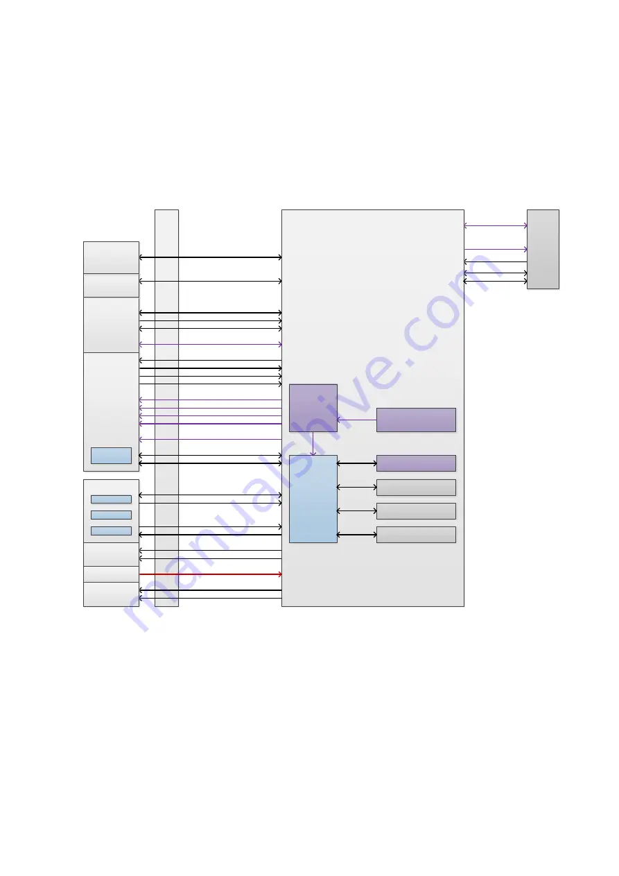
Engine board is equipped with pre-processing of beam data, scanning generator, primary clock on
front-end, ATGC circuit, probe management control, high-voltage switch control, etc. The board is
also considered as the engine of ultrasound service.
Mother
Board
TX_CLK
AFE_CLK
data bus
control bus
JTAG downstream
reset
reset status
rate
presents
manager communication
interrupts
PrbManager_JTAG
various signals
from/to probes. e.g. 4D/TEE
XCVR_REFCLK
PC module
PC Carrier Board
MF FPGA
ATGC Bus
present / UART
power
4D motor signals
temperature /
angle from TEE
ADC SPI
present/ID
config. status
Probe Board
Pen Probe
global reset
PCI-E bus
JTAG downstream
acoustic power
IO Board
Psychological
Signal Module
config. status
EC
TR Board
TR FPGA
Engine Board
DAC SPI
4D&TEE
Board
DC-DC Board
scan status
PHV sync
PHV Board
DSP
FPGA
Front End Clock Source
IQ DDR
Upload DDR
Clock
Distribution
ATGC
Clock
Control
Data Gathering DDR
BF_CLK
DDR IF
DDR IF
DDR IF
present / ID
Figure 4-5 Schematic diagram of engine board
The functions of engine board:
Summary of Contents for DC-68
Page 2: ......
Page 12: ......
Page 18: ......
Page 30: ......
Page 45: ...System Installation 3 15...
Page 54: ......
Page 72: ......
Page 90: ......
Page 108: ...8 2 Field Replaceable Unit 8 1 Explosive View A0 B0 C0 D0 E0 F0 G0...
Page 121: ...Field Replaceable Unit 8 15 8 2 5 Main Unit Assembly E0 E2 E4 E6 E5 E9 E8 E3 E7 E1...
Page 123: ...Field Replaceable Unit 8 17 E13 E22 E10 E17 E16 E14 E18 E19 E23 E20 E21 E15 E11 E12 E24...
Page 134: ......
Page 180: ......
Page 212: ......
Page 254: ......
Page 258: ......
Page 280: ......
Page 281: ...P N 046 011984 00 7 0...


