Structure and Assembly/Disassembly 9-35
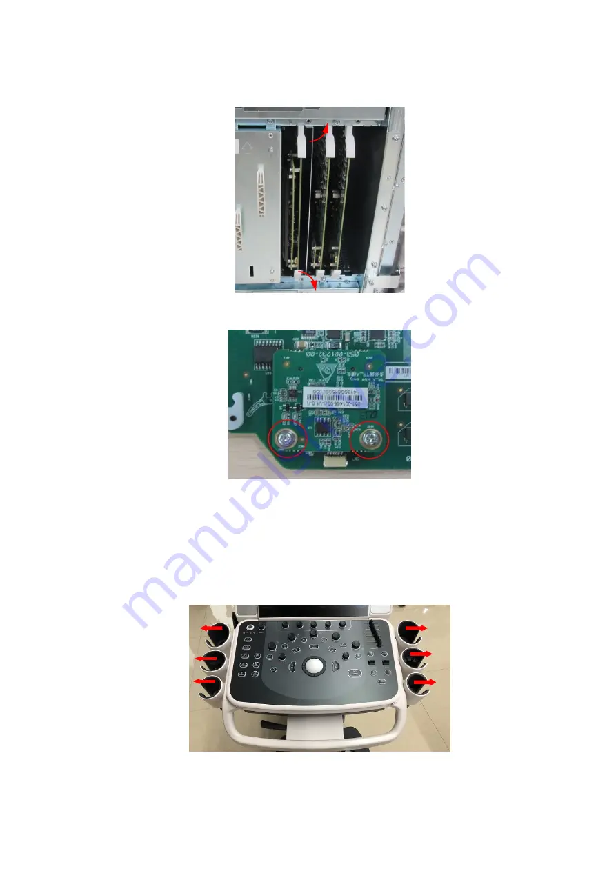
3. And remove TR board as shown in the figure below.
4. Unscrew two M3 X 8 screws to remove the material package of CW assembly.
9.3.21 Support Arm Assembly of the Control Panel
The disassembly tool: cross-headed screwdriver (M3, M4), sharp nose pliers, flat nose pliers.
1. Remove the holders on both sides. Press the clips inwards. Lift the holders to both sides to
remove them.
Summary of Contents for DC-68
Page 2: ......
Page 12: ......
Page 18: ......
Page 30: ......
Page 45: ...System Installation 3 15...
Page 54: ......
Page 72: ......
Page 90: ......
Page 108: ...8 2 Field Replaceable Unit 8 1 Explosive View A0 B0 C0 D0 E0 F0 G0...
Page 121: ...Field Replaceable Unit 8 15 8 2 5 Main Unit Assembly E0 E2 E4 E6 E5 E9 E8 E3 E7 E1...
Page 123: ...Field Replaceable Unit 8 17 E13 E22 E10 E17 E16 E14 E18 E19 E23 E20 E21 E15 E11 E12 E24...
Page 134: ......
Page 180: ......
Page 212: ......
Page 254: ......
Page 258: ......
Page 280: ......
Page 281: ...P N 046 011984 00 7 0...


