4 - CONTROLS AND INSTRUMENTS
4 - 18
4) MANUAL WEIGHING (E)
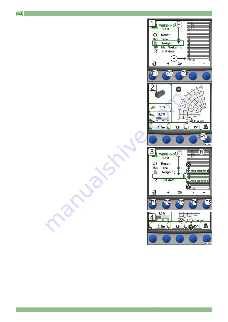
Use this control to manually weigh the load being lifted on the attachment. The
data measured by the system are shown in table 'B', from cell number 1 to cell
number 20. After 20 weighings all the values scroll up, and the next values are
displayed at the bottom of the table. The total at the bottom of table 'B' is always
the sum of all weighings, including the ones which are not displayed.
To carry out the manual weighing procedure you need to scroll the weighing
screen with button (P2) until you select 'WEIGHING'. Then press (P3) to confirm.
A tone confirms that the weighing procedure was successfully completed, and
the system stores the value in table 'B'.
To know the sum total of all weighings please refer to the figure next to the 'TOT'
inscription, which is shown in the bottom row of the table; this total increases up
to a maximum of 9999.99 t. (Fig. 1)
Press button (P1) to go back to the main screen.
You can also carry out a manual weighing procedure from the main screen by
pressing button (P5); a tone confirms that the weighing procedure was
successfully completed, and the system stores the value. On the main screen
you can also see the total of the weighings, whose value is shown under the load
chart in field (224). The manual weighing procedure can be carried out from the
main screen only if you have previously selected the 'MAN WEIGHING' item on
the weighing screen. (Fig. 2)
5) WEIGHING MODES (F)
Use this control to set the weighing mode:
1) MANUAL
2) AUTOMATIC
Is the manual mode selected, symbol 'X' appears with the 'MAN WEIGHING'
inscription next to it. Is the automatic mode selected, the 'Y' symbol appears with
the 'AUTO WEIGHING' inscription next to it. For the manual weighing procedure
please refer to the instructions provided in the previous step (MANUAL
WEIGHING 'E'), while for the automatic weighing please refer to the following
instructions.
Scroll the weighing screen with button (P2) until you select 'AUTO WEIGHING',
then press button (P3) to confirm. Now you can set a boom lift angle beyond
which the system automatically carries out a weighing. Such angle should be set
using buttons P4 (decrease) and P5 (increase), and should range between 0°
and 70°. Once these functions are set you need to press button (P1) and to go
back to the MAIN SCREEN, because the automatic weighing does not work in
the WEIGHING SCREEN (Fig. 3).
To confirm that the system was correctly set in the automatic mode, field (224)
on the main screen shows the 'Y' symbol and the value you selected for the
boom lift angle (in degrees).
In this way, whenever the telescopic boom is lifted beyond the angle you
selected, the system carries out an automatic weighing (emitting the corresponding tone), and stores the value in table 'B'. The
sum total of the weighings is always shown on the main screen, under the load chart and next to the 'TOT' inscription (Fig. 4).
In order to have a new automatic weighing available you need to lower the telescopic boom until it is 5° below the value you set
for the lift angle; if not, when you raise the telescopic boom again, the system will not carry out any automatic weighing.
Summary of Contents for P25.6
Page 2: ...04 2017 PUBLICATION DATE...
Page 4: ......
Page 6: ......
Page 21: ...2 MACHINE TECHNICAL SPECIFICATIONS 2 9...
Page 27: ...3 STICKERS WITH CONTROL DESCRIPTIONS LEAFLETS IN THE CABIN 3 3 STICKERS OF CONTROL PANEL P...
Page 28: ...3 STICKERS WITH CONTROL DESCRIPTIONS LEAFLETS IN THE CABIN 3 4 OUTSIDE CAB STICKERS...
Page 30: ......
Page 60: ......
Page 78: ......
Page 90: ...6 ORDINARY MAINTENANCE 6 12...
Page 114: ......
Page 120: ......
Page 138: ...9 HYDRAULIC CIRCUITS DIAGRAMS 9 2 HYDROSTATIC TRANSMISSION CIRCUIT...
Page 140: ...9 HYDRAULIC CIRCUITS DIAGRAMS 9 4 HYDRAULIC SYSTEM...
Page 142: ......
Page 143: ...10 ELECTRICAL SYSTEM 10 1 INDEX GENERAL FEATURES 2 BATTERY 2 FUSES 4 END OF CHAPTER 5...
Page 148: ......
Page 149: ...M2 M2 P256 AU 01 1...
Page 150: ...M2 2 M2 P256 AU 01...
Page 151: ...M2 M2 P256 AU 01 3...
Page 152: ...M2 4 M2 P256 AU 01...
Page 153: ...M2 M2 P256 AU 01 5...
Page 154: ...M2 6 M2 P256 AU 01...
Page 155: ...M2 M2 P256 AU 01 7...
Page 156: ...M2 8 M2 P256 AU 01...
Page 157: ...M2 M2 P256 AU 01 9...
Page 158: ...M2 10 M2 P256 AU 01...
Page 159: ...M2 M2 P256 AU 01 11...
Page 160: ...M2 12 M2 P256 AU 01...
Page 161: ...M2 M2 P256 AU 01 13...
Page 162: ......
Page 163: ...MODULE M3 ATTACHMENTS FOR MERLO ZM2 CARRIAGE...
Page 164: ......
Page 166: ......
Page 172: ......
Page 230: ...MODULE 3 SECTION 2 ATTACHMENTS 62 M M3 3 Z ZM M2 2 0 03 3 E EN N...
Page 231: ...ATTACHMENTS FOR MERLO ZM2 CARRIAGE M3...
Page 232: ......


