4 - CONTROLS AND INSTRUMENTS
4 - 15
• ACTIVATION OF THE GRAPHIC BAR FOR CONTROL SELECTION
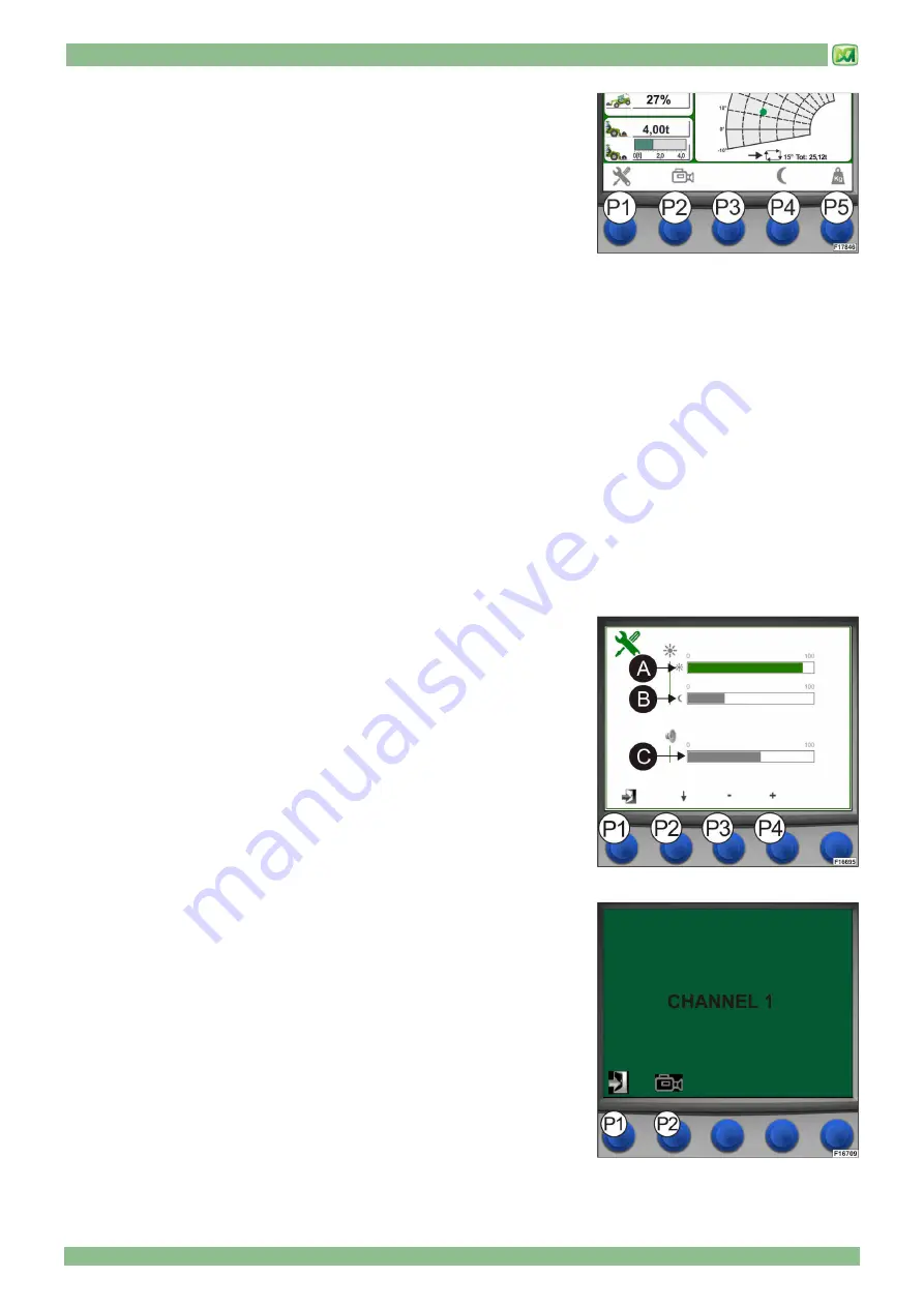
Display (D) of the load control system is equipped with a floating bar which
shows control buttons P1, P2, P3, P4 and P5. The activation of this floating bar
depends on the weighing mode selected by the operator:
1) In the 'AUTO WEIGHING' mode (see paragraph 'WEIGHING SCREEN'), when
one of the 5 selection buttons (P1, P2, P3, P4 or P5) is pressed, the system
activates the graphic bar at the bottom of display (D) where the executable
functions are shown. The operator has 5 seconds to press the button
corresponding to the function to be executed. If no selection button is pressed
within 5 seconds, the system deactivates the graphic bar.
2) In the 'MAN WEIGHING' mode (see paragraph 'WEIGHING SCREEN'), when one of the 4 selection buttons (P1, P2, P3 or
P4) is pressed, the system activates the graphic bar at the bottom of display (D) where the executable functions are shown.
The operator has 5 seconds to press the button corresponding to the function to be executed. If no selection button is pressed
within 5 seconds, the system deactivates the graphic bar.
If button P5 is pressed in the manual mode, it does not activate the graphic bar but it starts a weighing procedure for the load
being lifted (see paragraph 'MANUAL WEIGHING' (E)
The functions corresponding to the selection buttons are the following:
(P1): press button (P1) to activate the setup menu for display (D), where you can adjust both display brightness in the
daytime/night illumination mode and the volume of the loudspeaker.
(P2): press button (P2) to switch on the video camera installed on the machine (available as an option). Each time button (P2)
is pressed again, the system goes through all the video cameras available on the machine (check whether your machine
is equipped with optional video cameras)
(P3): this button does not activate any function on the machine
(P4): press button (P3) to activate the daytime/night illumination mode for display (D)
(P5): press button (P5) to activate the weighing screen (for further information please refer to the instructions provided in
paragraph 'WEIGHING SCREEN').
• DISPLAY SETUP (BUTTON P1)
Carry out the following operations to adjust the brightness of display (D) (both in
a daytime and in a night mode) and the volume of the loudspeaker:
-
activate the menu bar
-
press button (P1): a screen appears where you can adjust both display
brightness and volume
-
press button (P2) to select the graphic bar corresponding to the setting you
need to modify (in this order: daytime brightness (A), night brightness (B),
volume (C)
-
press buttons (P3) and (P4) to set the desired values for both brightness and
volume (they can both be adjusted from a minimum of 0 to a maximum of
100)
Press button (P1) to exit the setup screen for display (D).
• SELECTION OF THE VIDEO CAMERA (BUTTON P2)
Carry out the following operations to view the images from the video cameras
installed on your machine (available as options) on the screen of display (D) in
the cab:
-
activate the menu bar.
-
press button (P2): the system displays CHANNEL 1. Press button (P2) again
to change over to CHANNEL 2.
-
press button (P1) to go back to the main screen.
Summary of Contents for P25.6
Page 2: ...04 2017 PUBLICATION DATE...
Page 4: ......
Page 6: ......
Page 21: ...2 MACHINE TECHNICAL SPECIFICATIONS 2 9...
Page 27: ...3 STICKERS WITH CONTROL DESCRIPTIONS LEAFLETS IN THE CABIN 3 3 STICKERS OF CONTROL PANEL P...
Page 28: ...3 STICKERS WITH CONTROL DESCRIPTIONS LEAFLETS IN THE CABIN 3 4 OUTSIDE CAB STICKERS...
Page 30: ......
Page 60: ......
Page 78: ......
Page 90: ...6 ORDINARY MAINTENANCE 6 12...
Page 114: ......
Page 120: ......
Page 138: ...9 HYDRAULIC CIRCUITS DIAGRAMS 9 2 HYDROSTATIC TRANSMISSION CIRCUIT...
Page 140: ...9 HYDRAULIC CIRCUITS DIAGRAMS 9 4 HYDRAULIC SYSTEM...
Page 142: ......
Page 143: ...10 ELECTRICAL SYSTEM 10 1 INDEX GENERAL FEATURES 2 BATTERY 2 FUSES 4 END OF CHAPTER 5...
Page 148: ......
Page 149: ...M2 M2 P256 AU 01 1...
Page 150: ...M2 2 M2 P256 AU 01...
Page 151: ...M2 M2 P256 AU 01 3...
Page 152: ...M2 4 M2 P256 AU 01...
Page 153: ...M2 M2 P256 AU 01 5...
Page 154: ...M2 6 M2 P256 AU 01...
Page 155: ...M2 M2 P256 AU 01 7...
Page 156: ...M2 8 M2 P256 AU 01...
Page 157: ...M2 M2 P256 AU 01 9...
Page 158: ...M2 10 M2 P256 AU 01...
Page 159: ...M2 M2 P256 AU 01 11...
Page 160: ...M2 12 M2 P256 AU 01...
Page 161: ...M2 M2 P256 AU 01 13...
Page 162: ......
Page 163: ...MODULE M3 ATTACHMENTS FOR MERLO ZM2 CARRIAGE...
Page 164: ......
Page 166: ......
Page 172: ......
Page 230: ...MODULE 3 SECTION 2 ATTACHMENTS 62 M M3 3 Z ZM M2 2 0 03 3 E EN N...
Page 231: ...ATTACHMENTS FOR MERLO ZM2 CARRIAGE M3...
Page 232: ......


