


Patch
50
Xciter user manual
Note: the physical channel needs to be patched before you can set its mode.
7.
Each physical channel has three parameters:
•
Test value: this value is of no consequence to programming. It is merely a value that is applied to the
DMX output to test the presence of a device. This is very useful when patching a rig of PAR cans.
Because Xciter puts this test value on the output, you can see which PAR you are patching to the
selected fader. With this parameter you can set the intensity of the dimmer when testing it. We put it on
128 because some people may use 110V PAR lamps on 220V dimmer packs.
•
High limits: By default this value is set to 255, the highest possible value for a physical channel. If you
set this parameter to a lower value for a certain physical channel, Xciter will not send out a higher value
on that channel, even when you put the logical channel (fader) on a higher value. This is again very
useful if you want to prevent 220V dimmer packs from going past 110V.
•
Low Limits: By default this value is set to 0, the lowest possible value for a physical channel. If you set
this parameter to a higher value for a certain physical channel, the Xciter will not send out a lower value
on that channel, even when you put the logical channel (fader) on a lower value. This parameter is useful
when you want to put a preheat voltage on the light bulbs of your PAR cans.
To set these different parameters:
a)
Press {Test value}, {High limits} or {Low limits} to jump between the different parameters being
displayed. Example: Push the softkey until you see ‘Low limits’ next to it. This means the low limits of
the patched channels are currently displayed in the fader LCD.
b)
Use the fader to adjust the values. Example: Set the low limit of channel 101 to 30.
8.
There are some additional tools to in the dialog to accommodate easy navigation and display additional
information on the fader LCD.
With {Next used} you can jump directly to all the physical channels that are currently patched to the
selected logical channel.
With {Unit names} or {Channel names} you can toggle the display between the names of units and
channels. Note that the fader LCD also displays units from the fixture and DA patch as you scroll through
the DMX chain.
8.2.5.4
Soft patch, Limits
In the previous example of the soft patch we covered channel limits. Remember that when you added the
physical channel, the default limits and test values appeared on the fader display. In this section you will
discover an extra feature of the dimmer patch that allows you to set these defaults. When soft patching a
lot of channels, this will save you some work. But also take into account that these same defaults are used
when you are patching single channels the quick way (See example 1 of the dimmer patch).
Example: You are using 110V PAR cans on a 220V dimmer. Although you can set the limits in the soft
patch it is safer to set them using this limits option prior to patching. That way you are sure that all physical
channels you patch afterwards are set to the correct limits.
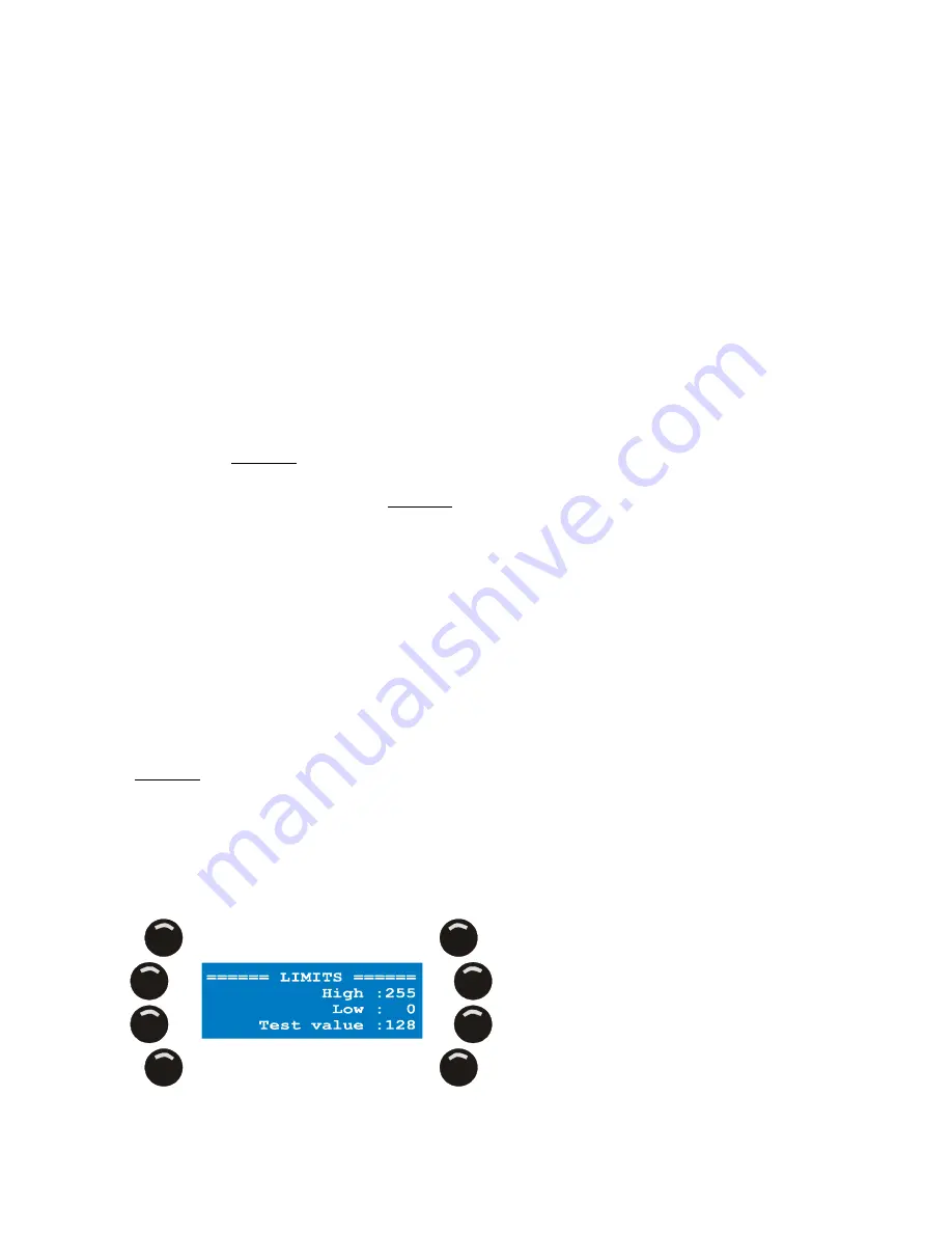
Warning: The default limits roll back to system default (High 255, Low 0, Test value 128) the moment you
leave the dimmer patch. So you need to set them to your desired defaults when you return to the dimmer
patch later and want to use defaults other then the system defaults.
1.
Press {Limits} in the dimmer patch menu.
2.
Press the softkey next to the parameter you wish to change.