28
7.5.3.2
Connecting an Enhanced Power Source PCB Controller with a LED PCB Power
Extension
To connect an enhanced power source - PCB Controller with a LED PCB power extension:
1.
Connect one end of the LED Power Control Wire to the
JP3
connector on the PCB Controller
,
and to the
JP3
connector on the Extension PCB
board on the other side.
2.
Connect one end of the High Power USB Cable to the
J5
connector on the
PCB Controller
board,
and to
the
J1
connector on the
Extension PCB board on the other side.
Note
: The LED Power Wire and the High Power USB cable come together in a bundle.
3.
Connect the 2 LED PCB Wire Extension cables to the Extension PCB
board (The LED PCB wire does not
have polarity), one cable to the
J3
connector, the other to the
J5
connector. Connect the other side of
the LED Wire extension cables to the LED PCB Wires on the Active Barrier.
Note
: The LED Power extension cable for systems containing more than 16 LED PCBs differs from LED wires for systems
containing less than 16 LED PCBs, in that it contains 2 wires, each wire connected to the Extension PCB on side (J5, J3),
and to a connector on the active barrier on the other side. The LED Power extension cable connectors are thicker than
regular LED wires connectors.
4.
Connect one end of the USB Power Cable to the
CN1
connector on the
Extension PCB
board, and the
other end to the PC.
5.
Connect the sensors to the PCB Controller (To connect sensors; see
Connecting the Sensors to the PCB
).
6.
Connect one end of the Power Supply cable to the
J2
connector on the
Extension PCB board, and the
other side to a
5v Adaptor
connected to a wall socket power supply (110v-220v).
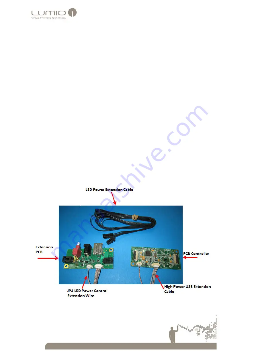
The following picture displays a PCB Controller connected to an Extension PCB
Figure 26 High Power PCB Controller with Extension PCB Controller


