background image


25 


3.


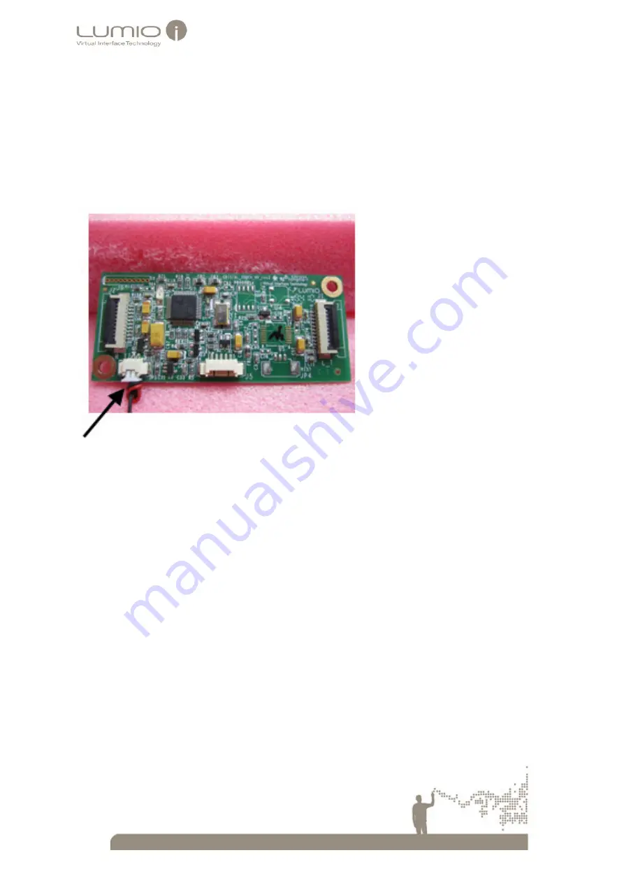
Insert the opposite 2 X Male LED wire extension cable connector into the Female connector marked JP3 

on the PCB Controller board. 

Note

:  


Ensure that the prongs of the 2 X Male connector fit correctly into the Female connector 


Ensure that the 2 X Male connector locks tight into the Female connector 

The following picture displays a LED PCB wire extension cable connected to the JP3 connector on the PCB 

Controller board. 

Figure 20 PCB Controller – LED Wire Extension Cable Connection 


Summary of Contents for Crystal Touch Series

Page 1: ...Integrator Guide Ver A5 7 2012...

Page 2: ...damages of any kind however incurred through the use of this product Lumio Inc reserves the right to make changes to any of its products in order to improve reliability design and performance The tex...

Page 3: ...2 Mounting Requirements 15 6 3 Mounting Touch Screens 16 6 3 1 Mounting Small Touch Screen Screens 16 6 3 2 Mounting Large Touch Screen Panels 17 Connecting the Touch Screen 19 7 7 1 Requirements 19 7...

Page 4: ...erage Test Failure 39 Appendix C Installing Crystal Touch Manager 40 13 13 1 Installing Crystal Touch Manager Quick Start guide 40 13 2 Multi Touch Digitizer Recognition 40 Appendix D Cleaning Materia...

Page 5: ...ntegrate or service Touch Screens before reading all safety and operation instructions Connect electrical components to a power supply that is properly grounded During integration or maintenance disco...

Page 6: ...ponents A The Illumination Control Signal supplied by the Crystal Touch PCB Controller PCB Controller to the Touch Screen panel The Illumination Control Signal turns the Touch Screen s Active Barrier...

Page 7: ...e featuring high accuracy high resolution and high sensitivity Each system includes four optical Sensors placed on the corners of the panel In two sensor systems the sensors are placed on the top corn...

Page 8: ...7 Work Flow 3 The following flowchart displays an overall view of the work flow and procedures required to integrate the Touch Screens into monitors Table 3 Workflow...

Page 9: ...ents Component Inspection Touch Screen Panel Verify that The Sensors are attached to the Touch Screen panel Each Sensors is attached to an FFC cable The Rod Holders are attached to the Touch Screen pa...

Page 10: ...ouch Screen glass panel requirements apply Prior to inspection clean the glass and ensure that finger prints and other foreign materials are removed Ensure that adhesive material such as glue is not e...

Page 11: ...2 Tempered Chemically Strengthened glass complies with UL 60950 1 test method Safety Laminated Glass complies with BS EN 14449 2005 Safety laminated glass complies with EN12600 Class 2 Type B2 test me...

Page 12: ...paque Bubble Accept 0 3 D 0 8 N 3 0 3 D 1 0 N 4 0 3 D 1 2 N 5 0 3 D 1 4 N 6 Reject D 0 8 N 3 D 1 0 N 4 D 1 2 N 5 D 1 4 N 6 Scratch Translucent Hair Line Accept 0 03 W 0 07 L 20 N 4 0 03 W 0 07 L 25 N...

Page 13: ...fect Style Defect Definition Acceptance Criteria Rejection CRITERIA Notes Corner Fragments X 2 5mm Y 2 5mm Z glass thickness X 2 5mm Y 2 5mm Z glass thickness Allowed only outside the active area Side...

Page 14: ...he sensors b Connect the LED PCB wire to the PCB Controller c Connect a Power Source 3 Connect the Touch Screen to a PC 4 Open Windows Paint Navigate to Start All Programs Accessories Paint 5 Using yo...

Page 15: ...http www rogerscorp com hpf bisco products 1 5 HT 800 aspx or 800 foam from Poron see http www poron jp en appli automotive5 html Silicon strip F12 Grade A dimensions 10mm x3mm Electrical tape 2 cm w...

Page 16: ...away from high voltage sources Keep the Sensors Flat Cables away from high voltage sources When using Flex Sensors o Ensure that no pressure bears on the Flex sensor o Ensure that the Flex sensors ar...

Page 17: ...Integrators 2 Remove the protecting cover of the tape Note Ensure that the Touch Screen and the monitor are clean and free of dust finger prints lint etc as they will be glued together and any dirt no...

Page 18: ...d ensure that no pressure is applied to them and take precautions to prevent them from being cut by components such as the glass 2 Align the bottom edge of the Touch Screen glass panel with the bottom...

Page 19: ...n a monitor Figure 6 Mounting Large Touch Screens on a Monitor The following picture displays a mounted Touch Screen on a monitor Note that the glass panel of the Touch Screen is mounted on the bezel...

Page 20: ...PCB Controller on page 24 Connecting the System s Power Source on page 26 7 2 Mounting the PCB Controller on the Monitor The position of the PCB Controller on the monitor is determined by the integra...

Page 21: ...e Failure to comply may lead to improper connectivity To connect the sensors to the FFC Flat cable 1 Open the roll of flat cables Figure 9 Flat Cables 2 Slide open the connector latch situated at the...

Page 22: ...of 3mm 5mm on the FFC at the cable end adjacent to the sensor The slack cable strain relief is necessary in order to prevent the flat cable disconnecting from the sensor connector if the Touch Screen...

Page 23: ...ional identification 2 Open the connector latch of the J2 connector 3 Insert the flat cable into the J2 connector Note Ensure that the flat cable is o Inserted as deeply as possible into the connector...

Page 24: ...side board of the PCB Controller Note The J4 connector is also marked RB Right Bottom on the PCB Controller board for additional identification 3 Connect the flat cable connected to the sensors on the...

Page 25: ...wire extension cable Figure 18 LED Wire Cables Note Both ends of the LED Wires are connected to 2 pin male connectors 2 Insert the 2 X Male LED wire connector into the Female connector located on the...

Page 26: ...sure that the prongs of the 2 X Male connector fit correctly into the Female connector Ensure that the 2 X Male connector locks tight into the Female connector The following picture displays a LED PCB...

Page 27: ...the power source 1 Connect the supplied USB cable to the USB connection marked J5 on the PCB Controller board 2 Connect the other side of the USB cable to the PC 7 5 2 Enhanced Power Source PCB Contr...

Page 28: ...tension PCB Controller to power up Touch Screens containing more than 16 LED PCBs Large sized monitors require Extension PCB as they include more than 16 LED PCBs Large sized monitors are defined as S...

Page 29: ...ension cables to the LED PCB Wires on the Active Barrier Note The LED Power extension cable for systems containing more than 16 LED PCBs differs from LED wires for systems containing less than 16 LED...

Page 30: ...rial cable The cable includes a 3 pin Male Serial connector on one side and a 9 pin RS 232 connector on the other side Figure 27 Serial Cable 2 Insert the Male Serial connector into the JP4 female con...

Page 31: ...r User guide 4 Run Crystal Touch Manager a Navigate to Start All Programs Crystal Touch Manager Crystal Touch Manager or select on the Desktop Launch Bar The Crystal Touch Manager Main window opens 5...

Page 32: ...ning agents of any respectable manufacturer o Isopropyl 99 o Isopropanol IPA Note For more information concerning the cleaning agents their properties usage safety and so on see http www lumio com out...

Page 33: ...Crystal Touch Manager 4 Navigate to Login Enter Administrator password from Lumio Administrator Scope The Scope window opens displaying only the signal received by the top left sensor Note The top le...

Page 34: ...point on the bezel Figure 32 Scope Window before touching Test PointFigure 33 Scope Window Signal drop while touching Test Point 6 Open Microsoft Paint 7 Draw a continuous rectangle on the Touch Scre...

Page 35: ...To test performance 1 Open Windows Paint Navigate to Start All Programs Accessories Paint 2 Using your finger draw lines and touch the screen with a finger or designated tool as displayed below Figur...

Page 36: ...ct the Touch Screen to the PC with a USB cable 2 Connect the monitor to the PC with a Display Cable such as hdmi vga and so on 3 Install the Crystal Touch Manager application on the PC with the suppli...

Page 37: ...creen the cross hair becomes gray The cross hair turns green when the touch is stable Calibration for the selected point is successful if the point turns blue and the calibration target moves to the n...

Page 38: ...The Calibration Download window appears even when you do not save the calibration file Figure 42 Calibration Download Window 12 Select Yes The Calibration OK message windows open 13 Select OK The cal...

Page 39: ...dow The Coverage Test window opens displaying fields for each sensor assembled on the Touch Screen two panes for Dual Sensor systems four panes for Quad Sensor systems Each field specifies the sensor...

Page 40: ...rage Test Failure The Coverage test fails if no curve and pixel values are displayed in a field during the test The following window describes a failed coverage test Figure 46 Failed Coverage Test Win...

Page 41: ...ing ways 1 Ensure that the Microsoft Touch functions are enabled a Navigate to Start Control Panel Pen and Touch b The Pen and Touch window opens c Select the Touch tab d The Touch Pane opens e Ensure...

Page 42: ...ning agents of any respectable manufacturer Isopropyl 99 Isopropanol IPA For more information concerning the cleaning agents their properties usage safety and so on see http www lumio com outgoing Doc...

Page 43: ...r Assy Rev 7 1 ASS05000025 Fast Dual Sensor High Power USB Controller Assy Rev 7 2 ASS05000027 Fast Dual Sensor High Power USB Serial Controller Assy Rev 7 3 ASS05000022 Fast Quad Sensor USB Controlle...

Page 44: ...able 5 pins to 5 pins Female connectors L 20cm WRE010500 0 Cable FFC 10C Pitch 1 0mm L 50cm WRE011000 0 Cable FFC 10C Pitch 1 0mm L 100cm WRE011600 0 Cable FFC 10C Pitch 1 0mm L 160cm WRE012000 0 Cabl...

Reviews: