79
WWW.LCMETER.COM
LCI40
Series IOM
6 oPeration
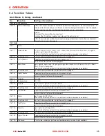
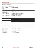
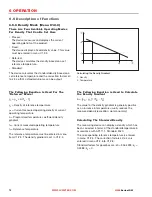
1. Flow
2. Time
3. Currently indicated flow
4. Display set to zero
5. Currently indicated flow
6. Positive hysteresis
7. Operating point
8. Negative hysteresis
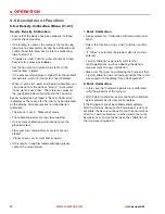
6.5.22 time Constant
To better process widely fluctuating measured values
in the device, the measured values are digitally filtered
to stabilise the output. The time constant can be
individually set for each output, the first line of the
display and the density measurement. However, keep
in mind that the degree of filtration affects the response
time of the device in the event of rapid changes.
6.5 description of Functions
6.5.21 low flow cutoff
The low flow cutoff can be individually set for each
output and each display line. If the low flow cutoff has
been activated, the respective output or display is set
to zero when the flow is below the low flow cutoff value
entered.
The value can either be entered as a percentage of the
nominal flow of the sensor or, in the case of a pulse
output, as a discrete flow value.
Two values must be entered. The first is for the
operating point of the sensor and the second is for
hysterisis. Condition: 1st value > 2nd value
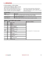
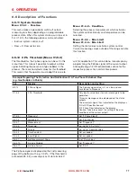
6.5.23 dual Phase Pulse output
A dual phase pulse or frequency output is often
required for custody transfer applications. This
operating mode requires 2 terminal pairs. Terminal
pairs A and B or D and B can be used.
In this case, perform the following settings:
•
C3.3.11: Phase shift to D or shift to A
•
All functions for output B are set using output D or
output A.
•
C3.5.11: Setting phase shift from output B relative to
D, if terminal pair D was selected in C3.3.11. 0°, 90°
or 180° are offered as options. C3.2.11: Setting the
phase shift from output B relative to A, if terminal pair
A was selected in C3.3.11 0°, 90° or 180° are offered
as options.
6.5.24 timeouts in Programming Mode
normal Menu Function
If no key has been pressed for 5 minutes in a normal
menu function, the display automatically switches to
measuring mode. All changes are lost.
test Function
In test mode, the test function is finished after 60
minutes.
GdC ir interface
If the GDC-IR connection is activated, it is cancelled
after 60 seconds if no connection is established. If the
connection is interrupted, the display can be operated
again after 60 seconds using the optical keys.
6.5.25 output hardware
Depending on the hardware modules used (see CG
number), it may be possible to change the output
options on terminals A, B, C or D in the menus C3.1.x.
For example: A pulse output to a frequency output or a
status output to a control input.
The available options are determined by the hardware
module used. It is not possible to change the type of
output, e.g. from active to passive.
Short Time Constant
Fast response times
Fluctuating reading
Long Time Constant
Slow response time
Stable reading
The time constant corresponds to the elapsed time
until 67% of the end value has been reached according
to a step function.

