


The rings are always centred on your vessel, and the
scale varies to suit your current chart range. Each
ring is labelled with the distance from your vessel.
By default range rings are switched off. Range rings
are not displayed in 3D view.
Switching range rings on and off
The range rings can be switched on and off by
following the steps below.
With the Chart application in 2D view:
1. Select
Menu
.
2. Select
Presentation
.
3. Select
Overlays
.
4. Select
Range Rings:
so that On is selected to
display Range Rings, or
5. Select
Range Rings:
so that Off is selected to
turn the Range Rings off.
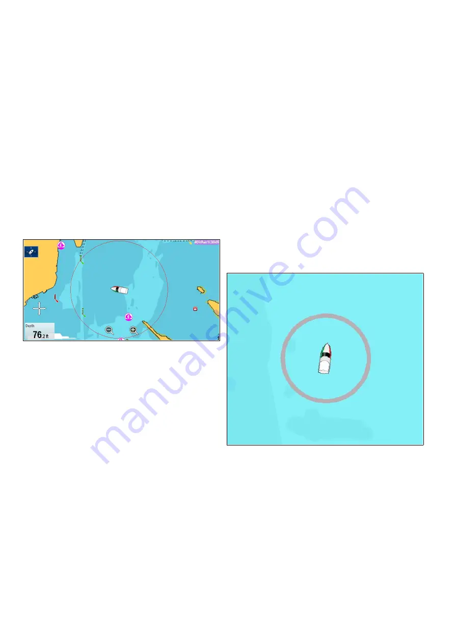
Safe Zone Ring
The chart application can display and configure a
MARPA / AIS safe zone ring.
The safe zone ring shares its configuration with the
Radar applications safe zone ring, however can be
displayed independently of the safe zone ring in the
Radar application.
If a MARPA or AIS target will reach the safe zone
ring within the time to safe zone selected an alarm
is sounded.
Showing the Safe Zone Ring in the Chart
application
To show the Safe Zone ring follow the instructions
below:
From the Chart application:
1. Select
Menu
.
2. Select
Presentation
.
3. Select
Overlays
.
4. Select
Safe Zone Ring
so that
Show
is selected.
Selecting Safe Zone Ring will switch the zone
ring between hidden to visible.
Setting up the Safe Zone Ring
You can adjust the Safe Zone Ring radius, the time
to Safe Zone and choose whether AIS targets trigger
the Safe Zone alarm from the Safe Zone Ring Set-up
menu.
The Safe Zone Set-up menu can be accessed as
follows:
• From the Radar application:
Menu > Zones >
Safe Zone Set-up
.
• From the Chart application with only the AIS
overlay enabled:
Menu > AIS Options > Safe
Zone > Safe Zone Set-up
.
• From the Chart application with only the Radar
overlay enabled:
Menu > Radar Options > Safe
Zone > Safe Zone Set-up
.
• From the Chart application with the AIS and Radar
overlays enabled:
Menu > Radar & AIS Options
> Safe Zone > Safe Zone Set-up
.
From the Safe Zone Set-up menu:
1. Select
Safe Zone Radius
.
i.
Select the required radius for the safe zone.
2. Select
Time to Safe Zone
.
i.
Select the required time period.
3. Select
AIS Alarm
so that On is highlighted.
Selecting AIS Alarm will switch the dangerous
target alarm between On and Off.
Fuel range rings
The fuel range ring gives an estimated range that
can be reached with the estimated fuel remaining
on-board.
The fuel range ring can be displayed graphically in
the chart application and indicates an estimated
range that can be reached with the:
• Current rate of fuel consumption.
• Estimated fuel remaining on-board.
• Course remaining in a straight line.
• Current speed maintained.
250
a Series / c Series / e Series
Summary of Contents for a125
Page 2: ......
Page 6: ......
Page 16: ...16 a Series c Series e Series ...
Page 43: ...13 GPS receiver 14 Thermal camera 15 Wireless connection Planning the installation 43 ...
Page 50: ...50 a Series c Series e Series ...
Page 82: ...82 a Series c Series e Series ...
Page 114: ...114 a Series c Series e Series ...
Page 120: ...120 a Series c Series e Series ...
Page 186: ...186 a Series c Series e Series ...
Page 190: ...190 a Series c Series e Series ...
Page 208: ...208 a Series c Series e Series ...
Page 230: ...230 a Series c Series e Series ...
Page 320: ...320 a Series c Series e Series ...
Page 340: ...340 a Series c Series e Series ...
Page 364: ...364 a Series c Series e Series ...
Page 420: ...420 a Series c Series e Series ...
Page 424: ...424 a Series c Series e Series ...
Page 434: ...434 a Series c Series e Series ...
Page 459: ......
Page 460: ...www raymarine com ...


