____________________________________________________________________________
L.S. Bilodeau inc.
281 Route 108 Est, Saint-Éphrem-de-Beauce, Quebec G0M 1R0
Tel.: 418 484-
2013 ▪ Fax: 418 484-2014 ▪
www.lsbilodeau.com
LS150
2015-09-18
Veuillez respecter les recommandations suivantes lors de la sélection et l’installation de la cheminée :
1)
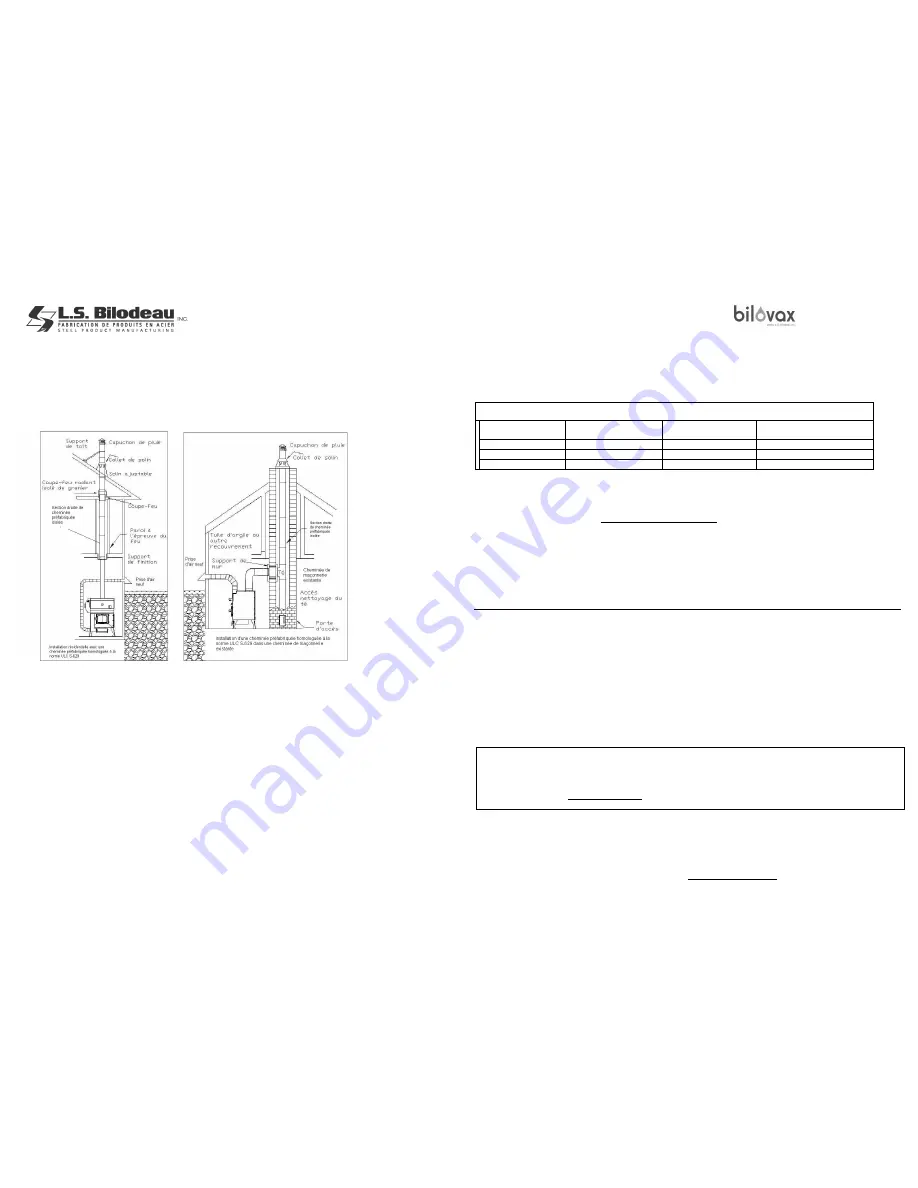
Le capuchon de pluie doit dépasser le toit d’au moins 90 cm (3′).
2)
La partie la plus haute de la cheminée doit dépasser toute partie de la bâtisse ou autre obstruction située dans un rayon de 3 m (10′) d’au
moins 60 cm (24")
3)
L’installation de la cheminée à l’intérieur des murs est fortement recommandée afin de permettre à celle-ci de conserver sa chaleur et ainsi
faciliter le tirage. Pour faciliter le tirage, nous vous recommandons également le système Novoclimat
MC
offert en option. (voir SECTION 10)
S’il n’y a pas d’autre alternative à une installation de la cheminée à l’extérieur des murs, on devra la recouvrir par une boîte à cheminée bien
isolée.
4)
Ne pas installer un autre appareil de chauffage sur la cheminée desservant le
Bilovax LS150
.
5)
Veuillez suivre à la lettre les instructions du fabricant de la cheminée lors de son installation
.
Illustration 4
Illustration 5
RACCORDS ET CONDUITES D’EAU
La chaudière
Bilovax LS150
a été conçue de façon à ce que sa restriction totale à l’écoulement de l’eau ne soit supérieure à plus de 3 m (10′) équivalents de
tuyau de 3,8 cm (1-½") approuvé pour opération continue à 100
o
C (212
o
F). Les raccordements d’entrée et de sortie de la chaudière seront de 3,8 cm (1-½")
et facilement adaptables au réseau de tuyaux du système de chauffage de l’édifice. Le conduit d’alimentation de la boucle de chauffage est situé sur le dessus
et le conduit de retour est situé dans la partie inférieure de la chaudière, il s’agit de tuyaux d’acier filetés (NPT mâle) où sont faits les raccords. La pose
d’unions sur les conduits d’alimentation et de retour est suggérée pour faciliter la dépose, si nécessaire, lors de l’entretien de la chaudière ou de la boucle de
chauffage. En cas de raccordements acier-cuivre, utiliser des raccords diélectriques afin de protéger la chaudière et la tuyauterie de l’action galvanique.
Prévoir une boucle de dérivation avec des robinets à bille (1/4 de tour) pour isoler la chaudière de la boucle de chauffage afin de ne pas être obligé de vider
la boucle de chauffage pour faire l’entretien. N’utiliser que des tuyaux propres et neufs pour raccorder la boucle de chauffage à la chaudière, les codes et
règlements locaux dictent exactement les types de tuyaux à utiliser. Il est préférable que la tuyauterie ne traverse pas un endroit non chauffé. Si l'on doit le
faire, il est important de l’isoler thermiquement et aussi de prévoir l’installation de câbles chauffants pour éliminer tout risque de gel à cet endroit. Même où
la tuyauterie de la boucle de chauffage traverse un espace chauffé, c’est une bonne pratique de l’isoler thermiquement afin de minimiser les pertes de
chaleur. Il est recommandé d’installer des thermomètres aussi bien sur le conduit d’alimentation que celui du retour de la boucle de chauffage. Bien obturer
toute ouverture non utilisée sur la chaudière.
SECTION 4. DESIGN CRITERIA OF THE CIRCULATING PUMP AND THE HEATING LOOP PIPING
Criteria 1:
▲T or
Temperature Drop of the heating medium in the heating loop
A simplified method is commonly used based on a ▲T of 20
°
F (11°C) between the supply and the return of the boiler. Such a method gives
good results when applied correctly. One must presume of a constant supply temperature less the return temperature from the heating loop.
For example, a boiler may have a supply temperature of 180
°
F and a return temperature of 160
°
F, the ▲T is then 20°F (11°C) 180 °F – 160
°F.
▲T or TEMPERATURE DROP THROUGH THE HEATING LOOP
Type of system
Boiler Supply
Temperature
Boiler Return
Temperature
▲T or
Temperature Drop
Through Boiler
Baseboards
190° to 140°F (88°- 60°C)
170° to 120°F (77°- 49°C)
20° to 40°F (11°- 22°C)
Cast-Iron Radi tors
160° to 130°F (71°- 55°C)
140° to 110°F (60°- 43°C)
20° to 40°F (11°- 22°C)
In-Floor Heating
130° to 90°F (55°- 32°C)
110° to 70°F (60°- 21°C)
20° to40°F (11°- 22°C)
N.B. The operating supply temperature of the boiler can vary from 180°F to 160°F
(
82°-
71°C) without any
problem of condensation but a plate heat
exchanger must be inserted between the boiler and the heating loop if the heating loop temperature differs from the boiler temperature.
The following formula helps to select the main circulating pump and other components of the heating loop depending on the type of
system to be installed.
Pump capacity in GPM(US) = Boiler heat output in BTU/h
500 X ▲T (supply temp. - return temp.)
The capacity of the pump is expressed in US gallons par minute (USGPM)
The required heat output of the boiler (in BTU/h) is the maximum heat output fed into the heating loop which can respond to the
maximum heating demand of a given building at it’s exterior design temperature.
(▲T) or Drop in temperature of the heat transfer medium is measured between the boiler supply and return.
For example, if the system is designed for a temperature drop (▲T) of 20°F (11
o
C) and has electric elements of 24 kW with a net heat
output of 82,000 BTU/h, the formula to calculate the pump flow is: 82,000 ÷ 10,000 = 8,2 USGPM, one must then install a pump with a
minimum flow of 9,0 USGPM. This will also be the pump flow required for the
Bilovax LS150
wood-fired boiler.
SECTION 5. VERIFICATION AND START-UP BY THE INSTALLER
Generalities:
The boiler and the heating loop must be in working order to carry out the following tests. Please consult this manual to understand the
lighting/starting and stopping procedures of the boiler. Make sure that all the air has been purged from the heating loop and boiler before
lighting it.
Inspection of water pipes and leak tests
:
It is recommended to clean the piping with a cleanser (check with your dealer) or plain water
to remove impurities that have accumulated in the pipes. Allow water to enter into the boiler and the heating loop. To purge all the air from the
boiler and the heating loop, pull on the lever of the safety relief valve and push on the plunger of the automatic air purge (by first removing
cap). When the boiler and the heating loop have been completely purged of air and filled with water, make sure that all the connections are
watertight and that water is not leaking or ooz
ing from the joints between the appliance and it’s inlet and outlet pipes and all other pipes of the
heating loop. If there are leaks, carefully seal all the leaks before proceeding with the other tests. Turn on the system for 4 to 6 hours and
drain. Refill with water or water / glycol.
WARNING FOR HEAT TRANSFER LIQUID
The heat transfer liquid must be water or any other nontoxic fluid which has a toxicity class or ratio of 1, as listed in
the current edition of the Toxicological Repertory of Commercial Products.
In a system with liquid water only, use natural water. We recommend distilled or softened water, when used in water /
glycol mixture, and that in the device Bilovax LS150 and in the piping network.
The liquid volume of the
Bilovax LS150
boiler is 25 imperial gallons (114 l).
Also read the WARNINGS mention and typical percentages of mix water / antifreeze at page 41-42.
Page 40
Page 7


