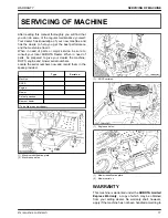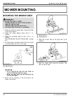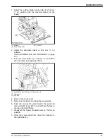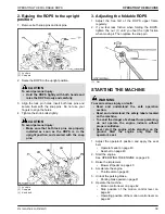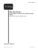
1. Adjust the cutting height control dial to 25.4 mm
(1 in.) position with the machine placed on the
board.
(1) Board
(2) Mower lift pedal
(P) “PUSH”
2. Adjust the anti-scalp rollers to 25.4 mm (1 in.)
position.
(See ADJUSTING THE CUTTING HEIGHT on page
46.)
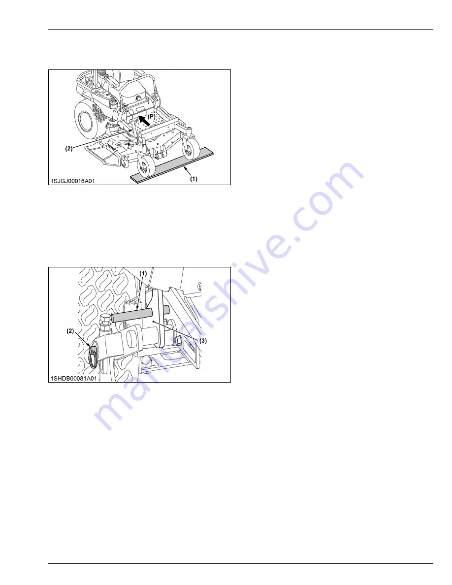
3. Put a Φ14 mm (0.55 in.) x 150 mm (6 in.) shaft in
the hole of the rear right side lift link.
(1) Shaft (Φ14 mm (0.55 in.) x 150 mm (6 in.))
(2) Clevis pin
(3) Lift link
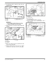
4. Remove the mower belt.
5. Remove 4 clevis pins mounting the mower deck.
6. Push the mower lift pedal toward the seat and
remove the Φ14 mm (0.55 in.) shaft from the hole in
the rear right side lift link.
7. Slowly let the mower lift pedal move to the full up
position.
8. Slide the mower deck from under the machine to
the right side of it.
MOWER MOUNTING
Z751KWi,Z781KWi,Z781KWTi
27
Summary of Contents for Z751KWi
Page 3: ...OPERATOR S MANUAL 1SJGJ00001A01 READ AND SAVE THIS MANUAL MODELS Z751KWi Z781KWi Z781KWTi ...
Page 15: ...SAFETY LABELS SAFE OPERATION 10 Z751KWi Z781KWi Z781KWTi ...
Page 16: ...SAFE OPERATION Z751KWi Z781KWi Z781KWTi 11 ...
Page 17: ...SAFE OPERATION 12 Z751KWi Z781KWi Z781KWTi ...
Page 18: ...SAFE OPERATION Z751KWi Z781KWi Z781KWTi 13 ...
Page 19: ...SAFE OPERATION 14 Z751KWi Z781KWi Z781KWTi ...
Page 21: ...16 Z751KWi Z781KWi Z781KWTi ...

