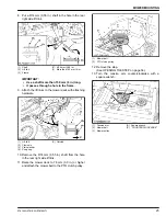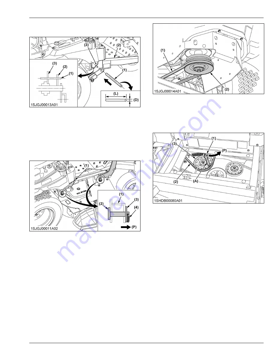
8. Put a Φ14 mm (0.55 in.) shaft in the hole in the rear
right side lift link.
(1) Shaft
(2) Lift link
(3) Frame
(D) Φ14 mm (0.55 in.)
(L) More than 150 mm (6 in.)
IMPORTANT :
• Use a shaft more than 150 mm (6 in.) long.
• It passes through a hole in the frame.
9. Attach the lift links to the mower deck with attaching
hardware.
(1) Lift link
(2) Clevis pin
(3) Plain washer
(4) Snap ring
(P) Outside
10. Remove the Φ14 mm (0.55 in.) shaft from the hole
in the rear right side lift link.
11. Raise the mower deck to 76 mm (3.0 in.) or higher
and attach the mower belt to the PTO clutch pulley.
(1) Mower belt
(2) PTO clutch pulley
12. Remove the step.
(See OPENING THE STEP on page 56.)
13. Turn the tension arm counterclockwise with a
square wrench.
(1) Tension arm
(2) Mower belt
(3) Mower pulley
(A) Square wrench
(P) “COUNTERCLOCK WISE”
MOWER MOUNTING
Z751KWi,Z781KWi,Z781KWTi
25
Summary of Contents for Z751KWi
Page 3: ...OPERATOR S MANUAL 1SJGJ00001A01 READ AND SAVE THIS MANUAL MODELS Z751KWi Z781KWi Z781KWTi ...
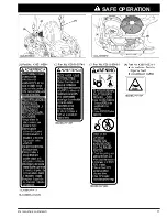
Page 15: ...SAFETY LABELS SAFE OPERATION 10 Z751KWi Z781KWi Z781KWTi ...
Page 16: ...SAFE OPERATION Z751KWi Z781KWi Z781KWTi 11 ...
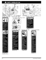
Page 17: ...SAFE OPERATION 12 Z751KWi Z781KWi Z781KWTi ...
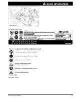
Page 18: ...SAFE OPERATION Z751KWi Z781KWi Z781KWTi 13 ...
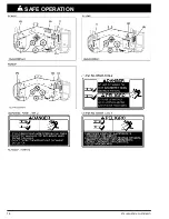
Page 19: ...SAFE OPERATION 14 Z751KWi Z781KWi Z781KWTi ...
Page 21: ...16 Z751KWi Z781KWi Z781KWTi ...

